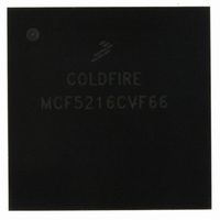
MCF5216CVF66 Freescale Semiconductor, MCF5216CVF66 Datasheet - Page 144

MCF5216CVF66
Manufacturer Part Number
MCF5216CVF66
Description
IC MPU 32BIT COLDF 256-MAPBGA
Manufacturer
Freescale Semiconductor
Series
MCF521xr
Datasheet
1.MCF5216CVM66J.pdf
(766 pages)
Specifications of MCF5216CVF66
Core Processor
Coldfire V2
Core Size
32-Bit
Speed
66MHz
Connectivity
CAN, EBI/EMI, I²C, SPI, UART/USART
Peripherals
DMA, LVD, POR, PWM, WDT
Number Of I /o
142
Program Memory Size
512KB (512K x 8)
Program Memory Type
FLASH
Ram Size
64K x 8
Voltage - Supply (vcc/vdd)
2.7 V ~ 3.6 V
Data Converters
A/D 8x12b
Oscillator Type
Internal
Operating Temperature
-40°C ~ 85°C
Package / Case
256-MAPBGA
Controller Family/series
ColdFire
Ram Memory Size
64KB
Embedded Interface Type
CAN, I2C, SPI, UART
No. Of Pwm Channels
8
Operating Temperature Range
-40°C To +85°C
No. Of Pins
256
Rohs Compliant
No
Package
256MA-BGA
Device Core
ColdFire
Family Name
MCF521x
Maximum Speed
66 MHz
Operating Supply Voltage
3.3 V
Data Bus Width
32 Bit
Number Of Programmable I/os
142
Interface Type
QSPI/UART/I2C/CAN
On-chip Adc
8-chx10-bit
Number Of Timers
8
Lead Free Status / RoHS Status
Contains lead / RoHS non-compliant
Eeprom Size
-
Available stocks
Company
Part Number
Manufacturer
Quantity
Price
Company:
Part Number:
MCF5216CVF66
Manufacturer:
FSC
Quantity:
1 670
Company:
Part Number:
MCF5216CVF66
Manufacturer:
Freescale Semiconductor
Quantity:
10 000
Part Number:
MCF5216CVF66
Manufacturer:
FREESCALE
Quantity:
20 000
Company:
Part Number:
MCF5216CVF66J
Manufacturer:
Freescale Semiconductor
Quantity:
10 000
- Current page: 144 of 766
- Download datasheet (9Mb)
Power Management
7.3.2.8
In wait and doze modes, the UART may generate an interrupt to exit the low-power modes.
In stop mode, the UARTs stop immediately and freeze their operation, register values, state machines, and
external pins. During this mode, the UART clocks are shut down. Coming out of stop mode returns the
UARTs to operation from the state prior to the low-power mode entry.
7.3.2.9
When the I
mode, the I
mode. For an interrupt to occur, the I2CR[IIE] bit must be set to enable interrupts, and the setting of the
I2SR[IIF] generates the interrupt signal to the CPU and interrupt controller. The setting of I2SR[IIF]
signifies either the completion of one byte transfer or the reception of a calling address matching its own
specified address when in slave receive mode.
In stop mode, the I
Upon exiting stop mode, the I
7.3.2.10 Queued Serial Peripheral Interface (QSPI)
In wait and doze modes, the queued serial peripheral interface (QSPI) may generate an interrupt to exit the
low-power modes.
In stop mode, the QSPI stops immediately and freezes operation, register values, state machines, and
external pins. During this mode, the QSPI clocks are shut down. Coming out of stop mode returns the QSPI
to operation from the state prior to the low-power mode entry.
7.3.2.11 DMA Timers (DMAT0–DMAT3)
In wait and doze modes, the DMA timers may generate an interrupt to exit a low-power mode. This
interrupt can be generated when the DMA Timer is in either input capture mode or reference compare
mode.
In input capture mode, where the capture enable (CE) field of the timer mode register (DTMR) has a
non-zero value and the DMA enable (DMAEN) bit of the DMA timer extended mode register (DTXMR)
is cleared, an interrupt is issued upon a captured input. In reference compare mode, where the output
reference request interrupt enable (ORRI) bit of DTMR is set and the DTXMR[DMAEN] bit is cleared,
an interrupt is issued when the timer counter reaches the reference value.
DMA timer operation is disabled in stop mode, but the DMA timer is unaffected by either the wait or doze
modes and may generate an interrupt to exit these modes. Upon exiting stop mode, the timer will resume
operation unless stop mode was exited by reset.
7-8
•
•
•
•
Clearing the transmit enable bit (TE) or the receiver enable bit (RE) disables UART functions.
The UARTs are unaffected by wait mode and may generate an interrupt to exit this mode.
Clearing the QSPI enable bit (SPE) disables the QSPI function.
The QSPI is unaffected by wait mode and may generate an interrupt to exit this mode.
2
2
C Module is enabled by the setting of the I2CR[IEN] bit and when the device is not in stop
UART Modules (UART0, UART1, and UART2)
I
C module is operable and may generate an interrupt to bring the device out of a low-power
2
C Module
2
C Module stops immediately and freezes operation, register values, and external pins.
MCF5282 and MCF5216 ColdFire Microcontroller User’s Manual, Rev. 3
2
C resumes operation unless stop mode was exited by reset.
Freescale Semiconductor
Related parts for MCF5216CVF66
Image
Part Number
Description
Manufacturer
Datasheet
Request
R
Part Number:
Description:
Manufacturer:
Freescale Semiconductor, Inc
Datasheet:
Part Number:
Description:
Manufacturer:
Freescale Semiconductor, Inc
Datasheet:
Part Number:
Description:
Manufacturer:
Freescale Semiconductor, Inc
Datasheet:
Part Number:
Description:
Manufacturer:
Freescale Semiconductor, Inc
Datasheet:
Part Number:
Description:
Manufacturer:
Freescale Semiconductor, Inc
Datasheet:
Part Number:
Description:
Manufacturer:
Freescale Semiconductor, Inc
Datasheet:
Part Number:
Description:
Manufacturer:
Freescale Semiconductor, Inc
Datasheet:
Part Number:
Description:
Manufacturer:
Freescale Semiconductor, Inc
Datasheet:
Part Number:
Description:
Manufacturer:
Freescale Semiconductor, Inc
Datasheet:
Part Number:
Description:
Manufacturer:
Freescale Semiconductor, Inc
Datasheet:
Part Number:
Description:
Manufacturer:
Freescale Semiconductor, Inc
Datasheet:
Part Number:
Description:
Manufacturer:
Freescale Semiconductor, Inc
Datasheet:
Part Number:
Description:
Manufacturer:
Freescale Semiconductor, Inc
Datasheet:
Part Number:
Description:
Manufacturer:
Freescale Semiconductor, Inc
Datasheet:
Part Number:
Description:
Manufacturer:
Freescale Semiconductor, Inc
Datasheet:


