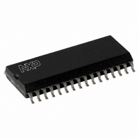
MFRC53001T/0FE,112 NXP Semiconductors, MFRC53001T/0FE,112 Datasheet - Page 112

MFRC53001T/0FE,112
Manufacturer Part Number
MFRC53001T/0FE,112
Description
IC MIFARE HS READER 32-SOIC
Manufacturer
NXP Semiconductors
Series
MIFARE®r
Specifications of MFRC53001T/0FE,112
Rf Type
Read Only
Frequency
13.56MHz
Features
ISO14443-A, ISO14443-B, ISO15693
Package / Case
32-SOIC (0.300", 7.50mm Width)
Product
RFID Readers
Operating Temperature Range
- 25 C to + 85 C
Lead Free Status / RoHS Status
Lead free / RoHS Compliant
Lead Free Status / RoHS Status
Lead free / RoHS Compliant, Lead free / RoHS Compliant
Other names
568-2223-5
935269692112
MFRC530
MFRC53T0FED
935269692112
MFRC530
MFRC53T0FED
Available stocks
Company
Part Number
Manufacturer
Quantity
Price
Company:
Part Number:
MFRC53001T/0FE,112
Manufacturer:
MICROCHIP
Quantity:
12 000
NXP Semiconductors
23. Figures
Fig 1.
Fig 2.
Fig 3.
Fig 4.
Fig 5.
Fig 6.
Fig 7.
Fig 8.
Fig 9.
Fig 10. Quartz clock connection . . . . . . . . . . . . . . . . . . .27
Fig 11. Receiver circuit block diagram . . . . . . . . . . . . . . .31
Fig 12. Automatic Q-clock calibration . . . . . . . . . . . . . . .32
Fig 13. Serial signal switch block diagram . . . . . . . . . . . .35
Fig 14. Crypto1 key handling block diagram . . . . . . . . . .38
Fig 15. Transmitting bit oriented frames . . . . . . . . . . . . .75
Fig 16. Timing for transmitting byte oriented frames . . . .76
Fig 17. Timing for transmitting bit oriented frames. . . . . .76
Fig 18. Card communication state diagram . . . . . . . . . . .81
Fig 19. EEPROM programming timing diagram. . . . . . . .83
Fig 20. Separate read/write strobe timing diagram . . . . .92
Fig 21. Common read/write strobe timing diagram . . . . .93
Fig 22. Timing diagram for common read/write strobe;
Fig 23. Timing diagram for SPI . . . . . . . . . . . . . . . . . . . .95
Fig 24. Application example circuit diagram: directly
Fig 25. TX control signals . . . . . . . . . . . . . . . . . . . . . . .100
Fig 26. RX control signals . . . . . . . . . . . . . . . . . . . . . . .101
Fig 27. ISO/IEC 14443 A receiving path Q-clock. . . . . .103
Fig 28. Package outline SOT287-1 . . . . . . . . . . . . . . . .104
MFRC530_33
Product data sheet
PUBLIC
MFRC530 block diagram . . . . . . . . . . . . . . . . . . . .4
MFRC530 pin configuration . . . . . . . . . . . . . . . . . .5
Connection to microprocessor: separate read
and write strobes . . . . . . . . . . . . . . . . . . . . . . . . . .8
Connection to microprocessor: common read
and write strobes . . . . . . . . . . . . . . . . . . . . . . . . . .9
Connection to microprocessor: EPP common
read/write strobes and handshake. . . . . . . . . . . . .9
Connection to microprocessor: SPI . . . . . . . . . . .10
Key storage format . . . . . . . . . . . . . . . . . . . . . . .16
Timer module block diagram . . . . . . . . . . . . . . . .22
The StartUp procedure. . . . . . . . . . . . . . . . . . . . .26
EPP . . . . . . . . . . . . . . . . . . . . . . . . . . . . . . . . . . .94
matched antenna . . . . . . . . . . . . . . . . . . . . . . . . .96
All information provided in this document is subject to legal disclaimers.
Rev. 3.3 — 6 July 2010
057433
ISO/IEC 14443 A Reader IC
MFRC530
© NXP B.V. 2010. All rights reserved.
112 of 115


