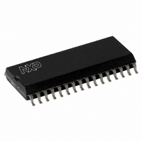
MFRC53001T/0FE,112 NXP Semiconductors, MFRC53001T/0FE,112 Datasheet - Page 14

MFRC53001T/0FE,112
Manufacturer Part Number
MFRC53001T/0FE,112
Description
IC MIFARE HS READER 32-SOIC
Manufacturer
NXP Semiconductors
Series
MIFARE®r
Specifications of MFRC53001T/0FE,112
Rf Type
Read Only
Frequency
13.56MHz
Features
ISO14443-A, ISO14443-B, ISO15693
Package / Case
32-SOIC (0.300", 7.50mm Width)
Product
RFID Readers
Operating Temperature Range
- 25 C to + 85 C
Lead Free Status / RoHS Status
Lead free / RoHS Compliant
Lead Free Status / RoHS Status
Lead free / RoHS Compliant, Lead free / RoHS Compliant
Other names
568-2223-5
935269692112
MFRC530
MFRC53T0FED
935269692112
MFRC530
MFRC53T0FED
Available stocks
Company
Part Number
Manufacturer
Quantity
Price
Company:
Part Number:
MFRC53001T/0FE,112
Manufacturer:
MICROCHIP
Quantity:
12 000
NXP Semiconductors
Table 16.
MFRC530_33
Product data sheet
PUBLIC
EEPROM
byte
address
10h
11h
12h
13h
14h
15h
16h
17h
18h
19h
1Ah
1Bh
1Ch
1Dh
1Eh
1Fh
20h
21h
22h
23h
24h
25h
26h
27h
28h
Register
address
10h
11h
12h
13h
14h
15h
16h
17h
18h
19h
1Ah
1Bh
1Ch
1Dh
1Eh
1Fh
20h
21h
22h
23h
24h
25h
26h
27h
28h
Shipment content of StartUp configuration file
9.2.2.2 Factory default StartUp register initialization file
Value
00h
58h
3Fh
3Fh
19h
13h
00h
00h
00h
73h
08h
ADh
FFh
1Eh
41h
00h
00h
06h
03h
63h
63h
00h
00h
00h
00h
The byte assignment is shown in
Table 15.
During the production tests, the StartUp register initialization file is initialized using the
default values shown in
values are written to the MFRC530’s registers.
EEPROM byte address
10h (block 1, byte 0)
11h
…
2Fh (block 2, byte 15)
Symbol
Page
TxControl
CwConductance
PreSet13
CoderControl
ModWidth
PreSet16
PreSet17
Page
RxControl1
DecoderControl
BitPhase
RxThreshold
BPSKDemControl
RxControl2
ClockQControl
Page
RxWait
ChannelRedundancy
CRCPresetLSB
CRCPresetMSB
PreSet25
MFOUTSelect
PreSet27
Page
Byte assignment for register initialization at start-up
All information provided in this document is subject to legal disclaimers.
Rev. 3.3 — 6 July 2010
Table
Description
transmitter pins TX1 and TX2 are switched off, bridge driver
configuration, modulator driven from internal digital circuitry
-
pulse width for Miller pulse encoding is set to standard configuration
-
-
free for user
bit-collisions always evaluate to HIGH in the data bit stream
MinLevel[3:0] and CollLevel[3:0] are set to maximum
use Q-clock for the receiver, automatic receiver off is switched on,
decoder is driven from internal analog circuitry
automatic Q-clock calibration is switched on
CRC preset value is set using ISO/IEC 14443 A
-
-
free for user
free for user
source resistance of TX1 and TX2 is set to minimum
ISO/IEC 14443 A coding is set
ISO/IEC 14443 A is set and internal amplifier gain is maximum
BitPhase[7:0] is set to standard configuration
ISO/IEC 14443 A is set
free for user
frame guard time is set to six bit-clocks
channel redundancy is set using ISO/IEC 14443 A
CRC preset value is set using ISO/IEC 14443 A
pin MFOUT is set LOW
16. During each power-up and initialization phase, these
057433
Table
15.
Register address
10h
11h
…
2Fh
ISO/IEC 14443 A Reader IC
MFRC530
© NXP B.V. 2010. All rights reserved.
Remark
skipped
copied
…
copied
14 of 115


