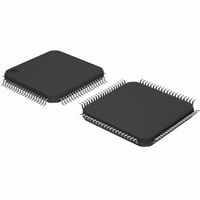
DP83849CVS/NOPB National Semiconductor, DP83849CVS/NOPB Datasheet - Page 22

DP83849CVS/NOPB
Manufacturer Part Number
DP83849CVS/NOPB
Description
IC TXRX ETHERNET PHY DUAL 80TQFP
Manufacturer
National Semiconductor
Type
Transceiverr
Specifications of DP83849CVS/NOPB
Number Of Drivers/receivers
2/2
Protocol
Ethernet
Voltage - Supply
3 V ~ 3.6 V
Mounting Type
Surface Mount
Package / Case
80-TQFP, 80-VQFP
Data Rate
100Mbps
Supply Voltage Range
3V To 3.6V
Logic Case Style
TQFP
No. Of Pins
80
Operating Temperature Range
0°C To +70°C
Msl
MSL 3 - 168 Hours
Filter Terminals
SMD
Rohs Compliant
Yes
Data Rate Max
10Mbps
For Use With
DP83849CVS-EVK - BOARD EVALUATION DP83849CVS
Lead Free Status / RoHS Status
Lead free / RoHS Compliant
Other names
*DP83849CVS
*DP83849CVS/NOPB
DP83849CVS
*DP83849CVS/NOPB
DP83849CVS
Available stocks
Company
Part Number
Manufacturer
Quantity
Price
Company:
Part Number:
DP83849CVS/NOPB
Manufacturer:
NS
Quantity:
618
Company:
Part Number:
DP83849CVS/NOPB
Manufacturer:
Texas Instruments
Quantity:
10 000
www.national.com
2.4.2 LED Direct Control
The DP83849I provides another option to directly control
any or all LED outputs through the LED Direct Control Reg-
ister (LEDCR), address 18h. The register does not provide
read access to LEDs.
2.5 Half Duplex vs. Full Duplex
The DP83849I supports both half and full duplex operation
at both 10 Mb/s and 100 Mb/s speeds.
Half-duplex relies on the CSMA/CD protocol to handle colli-
sions and network access. In Half-Duplex mode, CRS
responds to both transmit and receive activity in order to
maintain compliance with the IEEE 802.3 specification.
Since the DP83849I is designed to support simultaneous
transmit and receive activity it is capable of supporting full-
duplex switched applications with a throughput of up to 200
Mb/s per port when operating in 100BASE-TX. Because
the CSMA/CD protocol does not apply to full-duplex opera-
tion, the DP83849I disables its own internal collision sens-
ing and reporting functions and modifies the behavior of
Carrier Sense (CRS) such that it indicates only receive
activity. This allows a full-duplex capable MAC to operate
properly.
All modes of operation (100BASE-TX, 10BASE-T) can run
either half-duplex or full-duplex. Additionally, other than
Figure 3. AN Strapping and LED Loading Example
GND
AN_EN_A
= 0
AN1_A = 1
AN0_A = 1
VCC
22
CRS and Collision reporting, all remaining MII signaling
remains the same regardless of the selected duplex mode.
It is important to understand that while Auto-Negotiation
with the use of Fast Link Pulse code words can interpret
and configure to full-duplex operation, parallel detection
can not recognize the difference between full and half-
duplex from a fixed 10 Mb/s or 100 Mb/s link partner over
twisted pair. As specified in the 802.3u specification, if a
far-end link partner is configured to a forced full duplex
100BASE-TX ability, the parallel detection state machine in
the partner would be unable to detect the full duplex capa-
bility of the far-end link partner. This link segment would
negotiate to a half duplex 100BASE-TX configuration
(same scenario for 10Mb/s).
2.6 Internal Loopback
The DP83849I includes a Loopback Test mode for facilitat-
ing system diagnostics. The Loopback mode is selected
through bit 14 (Loopback) of the Basic Mode Control Reg-
ister (BMCR). Writing 1 to this bit enables MII transmit data
to be routed to the MII receive outputs. Loopback status
may be checked in bit 3 of the PHY Status Register
(PHYSTS). While in Loopback mode the data will not be
transmitted onto the media. To ensure that the desired
operating mode is maintained, Auto-Negotiation should be
disabled before selecting the Loopback mode.
2.7 BIST
The DP83849I incorporates an internal Built-in Self Test
(BIST) circuit to accommodate in-circuit testing or diagnos-
tics. The BIST circuit can be utilized to test the integrity of
the transmit and receive data paths. BIST testing can be
performed with the part in the internal loopback mode or
externally looped back using a loopback cable fixture.
The BIST is implemented with independent transmit and
receive paths, with the transmit block generating a continu-
ous stream of a pseudo random sequence. The user can
select a 9 bit or 15 bit pseudo random sequence from the
PSR_15 bit in the PHY Control Register (PHYCR). The
received data is compared to the generated pseudo-ran-
dom data by the BIST Linear Feedback Shift Register
(LFSR) to determine the BIST pass/fail status.
The pass/fail status of the BIST is stored in the BIST status
bit in the PHYCR register. The status bit defaults to 0 (BIST
fail) and will transition on a successful comparison. If an
error (mis-compare) occurs, the status bit is latched and is
cleared upon a subsequent write to the Start/Stop bit.
For transmit VOD testing, the Packet BIST Continuous
Mode can be used to allow continuous data transmission,
setting BIST_CONT_MODE, bit 5, of CDCTRL1 (1Bh).
The number of BIST errors can be monitored through the
BIST Error Count in the CDCTRL1 (1Bh), bits [15:8].


