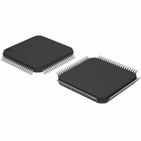
DP83849CVS/NOPB National Semiconductor, DP83849CVS/NOPB Datasheet - Page 29

DP83849CVS/NOPB
Manufacturer Part Number
DP83849CVS/NOPB
Description
IC TXRX ETHERNET PHY DUAL 80TQFP
Manufacturer
National Semiconductor
Type
Transceiverr
Specifications of DP83849CVS/NOPB
Number Of Drivers/receivers
2/2
Protocol
Ethernet
Voltage - Supply
3 V ~ 3.6 V
Mounting Type
Surface Mount
Package / Case
80-TQFP, 80-VQFP
Data Rate
100Mbps
Supply Voltage Range
3V To 3.6V
Logic Case Style
TQFP
No. Of Pins
80
Operating Temperature Range
0°C To +70°C
Msl
MSL 3 - 168 Hours
Filter Terminals
SMD
Rohs Compliant
Yes
Data Rate Max
10Mbps
For Use With
DP83849CVS-EVK - BOARD EVALUATION DP83849CVS
Lead Free Status / RoHS Status
Lead free / RoHS Compliant
Other names
*DP83849CVS
*DP83849CVS/NOPB
DP83849CVS
*DP83849CVS/NOPB
DP83849CVS
Available stocks
Company
Part Number
Manufacturer
Quantity
Price
Company:
Part Number:
DP83849CVS/NOPB
Manufacturer:
NS
Quantity:
618
Company:
Part Number:
DP83849CVS/NOPB
Manufacturer:
Texas Instruments
Quantity:
10 000
3.5.4 Strapped Extender Mode
The DP83849I provides a simple strap option to automati-
cally configure both channels for Extender Mode with no
device
EXTENDER_EN Strap can be used in conjunction with the
Auto-Negotiation Straps (AN_EN, AN0, AN1), the RMII
Mode Strap to allow many possible configurations. If
3.5.5 Notes and Restrictions
— Extender: Both channels must be operating at the same
— Broadcast TX MII Port Mode: To ensure synchronous
— RMII Mode: Both Channels must have RMII Mode en-
— 10Base-T Serial Mode: This MAC-side mode, also
— CRS Assignment: When a channel is not in RMII Mode,
speed (10 or 100Mb). This can be accomplished using
straps or channel register controls. Both channels must
be in Full Duplex mode. Both channels must either be in
RMII Mode (RBR:RMII_EN = 1) or full Single Clock MII
Mode (RBR:SCMII_RX = 1 and RBR:SCMII_TX = 1) to
ensure synchronous operation. If only one RX to TX path
is enabled, SCMII_RX in the RX channel (RBR register
17h bit 7) and SCMII_TX in the TX channel (RBR regis-
ter 17h bit 6) must be set to 1.
operation, both channels must be in RMII Mode (RBR
register 17h bit 5 = 1) or in Single Clock TX MII Mode
(RBR register 17h bit 6 = 1). Both channels must be op-
erating at the same speed (10 or 100Mb). Both channels
must be in Full Duplex mode to ensure no collisions are
seen. This is because in Single Clock TX MII Mode, a
collision on one PHY channel would cause both chan-
nels to send the Jam pattern.
abled or disabled concurrently due to the internal refer-
ence clocking scheme. In Full Port Swap Mode,
Channels are not required to have a common speed.
known as Serial Network Interface (SNI), may not be
used when both channels share data connections (Ex-
tender or Broadcast TX MII Port). This is due to the re-
quirement of synchronous operation between channels,
which is not supported in SNI Mode.
its associated CRS pin is sourced from the transmitter
and controlled by the TX MII Port Assignment, bits [10:9]
of RBR (17h). When a channel is in RMII Mode, the as-
100Mb Copper Extender
10Mb Copper Extender
register
Mode
configuration
Table 11. Common Strapped Extender Mode Configurations
necessary.
The
Both channels are forced to 100Mb Full Duplex
Both channels are forced to 10Mb Full Duplex
29
Extender Mode is strapped but RMII Mode is not, both
channels will automatically be configured for Single Clock
MII Receive and Transmit Modes. The optional use of
RMII Mode in conjunction with Extender Mode allows flexi-
bility in the system design.
Several common configurations are shown in Table 11.
— Output Enables: Flexible MII Port Assignment does not
— Test Modes: Test modes are not designed to be com-
— LED Assignment: LEDs are associated with their re-
— Straps: Strap pins are always associated with their re-
— Port Isolate Mode: Each MII port’s Isolate function, bit
— Energy Detect and Powerdown Modes: The output
sociated CRS pin is sourced from the receiver and con-
trolled by the RX MII Port Assignment, bits [12:11] of
RBR (17h).
control signal output enables.
patible with Flexible MII Port Selection, which assumes
default MII pin directions.
spective digital channels, and therefore do not get
mapped to alternate channels. For example, assertion
of LED_LINK_A indicates valid link status for Channel A
independent of the MII Port Assignment.
spective channel, i.e. a strap on RX_ER_A is used by
Channel A.
10 of BMCR (00h) is always associated with its respec-
tive channel, i.e. the Isolate function for Port A is always
controlled by Channel A’s BMCR (00h). Due to the var-
ious possible combinations of TX and RX port selection,
it may not be advisable to place a port in Isolate mode.
enables for each MII port are always controlled by the re-
spective channel Energy Detect and Powerdown func-
tions. These functions should be disabled whenever an
MII port is in use but not assigned to its default channel.
Note that Extender/Media Converter modes allow the
use of Energy Detect and Powerdown modes if the RX
MII ports are not in use.
Auto-Negotiation Straps
www.national.com


