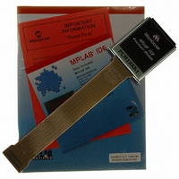
PCM18XK1 Microchip Technology, PCM18XK1 Datasheet - Page 235

PCM18XK1
Manufacturer Part Number
PCM18XK1
Description
MODULE PROC PIC18F8680,6680,8565
Manufacturer
Microchip Technology
Datasheet
1.PCM18XK1.pdf
(496 pages)
Specifications of PCM18XK1
Accessory Type
Processor Module
Lead Free Status / RoHS Status
Not applicable / Not applicable
For Use With/related Products
ICE2000
For Use With
ICE2000 - EMULATOR MPLAB-ICE 2000 POD
Lead Free Status / Rohs Status
Lead free / RoHS Compliant
- Current page: 235 of 496
- Download datasheet (9Mb)
18.1
The BRG is a dedicated 8-bit or 16-bit generator that
supports both the Asynchronous and Synchronous
modes of the USART. By default, the BRG operates in
8-bit mode; setting the BRG16 bit (BAUDCON<3>)
selects 16-bit mode.
The SPBRGH:SPBRG register pair controls the period
of a free-running timer. In Asynchronous mode, bits
BRGH (TXSTA<2>) and BRG16 also control the baud
rate. In Synchronous mode, bit BRGH is ignored.
Table 18-1 shows the formula for computation of the
baud rate for different USART modes which only apply
in Master mode (internally generated clock).
Given the desired baud rate and F
integer value for the SPBRGH:SPBRG registers can be
calculated using the formulas in Table 18-1. From this,
TABLE 18-1:
EXAMPLE 18-1:
TABLE 18-2:
2004 Microchip Technology Inc.
Legend: x = Don’t care, n = Value of SPBRGH:SPBRG register pair
TXSTA
RCSTA
BAUDCON
SPBRGH
SPBRG
Legend:
For a device with F
Desired Baud Rate
Solving for SPBRGH:SPBRG:
Calculated Baud Rate= 16000000/(64 (25 + 1))
Error
Name
SYNC
0
0
0
0
1
1
USART Baud Rate Generator (BRG)
x = unknown, - = unimplemented, read as ‘0’. Shaded cells are not used by the BRG.
Configuration Bits
Baud Rate Generator Register, High Byte
Baud Rate Generator Register, Low Byte
CSRC
SPEN
Bit 7
—
X
BAUD RATE FORMULAS
BRG16
REGISTERS ASSOCIATED WITH BAUD RATE GENERATOR
OSC
0
0
1
1
0
1
= F
= ((F
= ((16000000/9600)/64) – 1
= [25.042] = 25
= 9615
= (Calculated Baud Rate – Desired Baud Rate)/Desired Baud Rate
= (9615 – 9600)/9600 = 0.16%
CALCULATING BAUD RATE ERROR
RCIDL
Bit 6
RX9
of 16 MHz, desired baud rate of 9600, Asynchronous mode, 8-bit BRG:
TX9
OSC
OSC
/(64 ([SPBRGH:SPBRG] + 1))
/Desired Baud Rate)/64) – 1
SREN
TXEN
Bit 5
BRGH
—
0
1
0
1
x
x
OSC
, the nearest
CREN
SYNC
SCKP
Bit 4
PIC18F6585/8585/6680/8680
SENDB
ADDEN
BRG16
16-bit/Asynchronous
16-bit/Asynchronous
Bit 3
BRG/USART Mode
8-bit/Asynchronous
8-bit/Asynchronous
16-bit/Synchronous
8-bit/Synchronous
BRGH
FERR
Bit 2
—
the error in baud rate can be determined. An example
calculation is shown in Example 18-1. Typical baud
rates and error values for the various Asynchronous
modes are shown in Table 18-2. It may be advantageous
to use the high baud rate (BRGH = 1) or the 16-bit BRG
to reduce the baud rate error, or achieve a slow baud
rate for a fast oscillator frequency.
Writing a new value to the SPBRGH:SPBRG registers
causes the BRG timer to be reset (or cleared). This
ensures the BRG does not wait for a timer overflow
before outputting the new baud rate.
18.1.1
The data on the RC7/RX/DT pin is sampled three times
by a majority detect circuit to determine if a high or a
low level is present at the RX pin.
TRMT
OERR
WUE
Bit 1
SAMPLING
ABDEN
RX9D
TX9D
Bit 0
0000 0010
0000 000x
-1-0 0-00
0000 0000
0000 0000
Baud Rate Formula
POR, BOR
Value on
F
F
F
OSC
OSC
OSC
/[64 (n + 1)]
/[16 (n + 1)]
/[4 (n + 1)]
DS30491C-page 233
other Resets
Value on all
0000 0010
0000 000x
-1-0 0-00
0000 0000
0000 0000
Related parts for PCM18XK1
Image
Part Number
Description
Manufacturer
Datasheet
Request
R

Part Number:
Description:
Manufacturer:
Microchip Technology Inc.
Datasheet:

Part Number:
Description:
Manufacturer:
Microchip Technology Inc.
Datasheet:

Part Number:
Description:
Manufacturer:
Microchip Technology Inc.
Datasheet:

Part Number:
Description:
Manufacturer:
Microchip Technology Inc.
Datasheet:

Part Number:
Description:
Manufacturer:
Microchip Technology Inc.
Datasheet:

Part Number:
Description:
Manufacturer:
Microchip Technology Inc.
Datasheet:

Part Number:
Description:
Manufacturer:
Microchip Technology Inc.
Datasheet:

Part Number:
Description:
Manufacturer:
Microchip Technology Inc.
Datasheet:


