EVAL-ADT7411EBZ Analog Devices Inc, EVAL-ADT7411EBZ Datasheet - Page 8
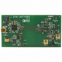
EVAL-ADT7411EBZ
Manufacturer Part Number
EVAL-ADT7411EBZ
Description
BOARD EVALUATION FOR ADT7411
Manufacturer
Analog Devices Inc
Datasheet
1.ADT7411ARQZ.pdf
(36 pages)
Specifications of EVAL-ADT7411EBZ
Sensor Type
Temperature
Sensing Range
-40°C ~ 120°C
Interface
DSP, I²C, MICROWIRE, QSPI, SMBus, SPI
Sensitivity
±0.5°C
Voltage - Supply
2.7 V ~ 5.5 V
Embedded
No
Utilized Ic / Part
ADT7411
Lead Free Status / RoHS Status
Lead free / RoHS Compliant


ADT7411
PIN CONFIGURATION AND FUNCTIONAL DESCRIPTIONS
Table 4. Pin Function Descriptions
Pin
No.
1
2
3
4
5
6
7
8
9
10
11
12
13
14
15
16
Mnemonic
AIN6
AIN5
NC
CS
GND
V
D+/AIN1
D−/AIN2
AIN3
INT/INT
DOUT/ADD
SDA/DIN
SCL/SCLK
AIN4
AIN8
AIN7
DD
Description
Analog Input. Single-ended analog input channel. Input range is 0 V to 2.25 V or 0 V to V
Analog Input. Single-ended analog input channel. Input range is 0 V to 2.25 V or 0 V to V
No Connection.
SPI—Active Low Control Input. This is the frame synchronization signal for the input data. When CS goes low, it
enables the input register and data is transferred in on the rising edges and out on the falling edges of the subsequent
serial clocks. It is recommended that this pin be tied high to V
Ground Reference Point for All Circuitry on the Part. Analog and digital ground.
Positive Supply Voltage, 2.7 V to 5.5 V. The supply should be decoupled to ground.
Positive Connection to External Temperature Sensor/Analog Input. Single-ended analog input channel.
Input range is 0 V to 2.25 V or 0 V to 5 V.
Negative Connection to External Temperature Sensor/Analog Input. Single-ended analog input channel.
Input range is 0 V to 2.25 V or 0 V to 5 V.
Analog Input. Single-ended analog input channel. Input range is 0 V to 2.25 V or 0 V to V
Overlimit Interrupt. The output polarity of this pin can be set to give an active low or active high interrupt when
temperature, V
DOUT—SPI Serial Data Output. Logic output. Data is clocked out of any register at this pin. Data is clocked out on the
falling edge of SCLK. Open-drain output needs a pull-up resistor.
ADD—I
floating gives the Address 1001 010 and setting it high gives the Address 1001 011. The I
ADD pin is not latched by the device until after this address has been sent twice. On the eighth SCL cycle of the
second valid communication, the serial bus address is latched in. Any subsequent changes on this pin have no
effect on the I
SDA—I
drain configuration needs a pull-up resistor.
DIN—SPI Serial Data Input. Serial data to be loaded into the part’s registers is provided on this input. Data is
clocked into a register on the rising edge of SCLK. An open-drain configuration needs a pull-up resistor.
Serial Clock Input. This is the clock input for the serial port. The serial clock is used to clock data out of any register
of the ADT7411 and to clock data into any register that can be written to. An open-drain configuration needs a pull-
up resistor.
Analog Input. Single-ended analog input channel. Input range is 0 V to 2.25 V or 0 V to V
Analog Input. Single-ended analog input channel. Input range is 0 V to 2.25 V or 0 V to V
Analog Input. Single-ended analog input channel. Input range is 0 V to 2.25 V or 0 V to V
2
2
C Serial Data Input. I
C Serial Bus Address Selection Pin. Logic input. A low on this pin gives the Address 1001 000, while leaving it
2
C serial bus address.
DD
, or AIN limits are exceeded. Default is active low. Open-drain output needs a pull-up resistor.
2
C serial data to be loaded into the part’s registers is provided on this input. An open-
D+/AIN1
D–/AIN2
AIN5
AIN6
GND
V
NC
CS
DD
Figure 6. Pin Configuration
1
2
3
4
5
6
7
8
NC = NO CONNECT
Rev. B | Page 8 of 36
(Not to Scale)
ADT7411
TOP VIEW
16
15
14
13
12
11
10
9
AIN7
AIN8
AIN4
SCL/SCLK
SDA/DIN
DOUT/ADD
INT/INT
AIN3
DD
when operating the serial interface in I
DD
DD
DD
DD
DD
DD
2
C address set up by the
.
.
.
.
.
.
2
C mode.
Related parts for EVAL-ADT7411EBZ
Image
Part Number
Description
Manufacturer
Datasheet
Request
R


Part Number:
Description:
BOARD EVAL FOR SI270X-A
Manufacturer:
Silicon Laboratories Inc
Datasheet:

Part Number:
Description:
BUCK CONV REF DESIGN KIT IP1201
Manufacturer:
International Rectifier
Datasheet:
Part Number:
Description:
BOARD DEMO SYNC DUAL BUCK CNVTER
Manufacturer:
International Rectifier
Datasheet:
Part Number:
Description:
BOARD DEMO SYNC BUCK CONVETER
Manufacturer:
International Rectifier
Datasheet:

Part Number:
Description:
EVALBOARD/EB Omnidirectional microphone - Analog
Manufacturer:
Analog Devices
Datasheet:
Part Number:
Description:
EVALBOARD/EB Omnidirectional microphone - Analog
Manufacturer:
Analog Devices
Datasheet:


Part Number:
Description:
BOARD EVAL LED DRIVER LT3756
Manufacturer:
Linear Technology
Datasheet:

Part Number:
Description:
BOARD EVAL FOR AD7741/7742
Manufacturer:
Analog Devices Inc
Datasheet:

Part Number:
Description:
±1.7g Dual-Axis IMEMS Accelerometer Evaluation Board
Manufacturer:
Analog Devices Inc
Datasheet:

Part Number:
Description:
IC MULTIPLIER ANALOG 8-SOIC T/R
Manufacturer:
Analog Devices Inc
Datasheet:

Part Number:
Description:
IC ANALOG MULTIPLIER 8-DIP
Manufacturer:
Analog Devices Inc
Datasheet:
Part Number:
Description:
IC ANALOG MULTIPLIER 8-SOIC
Manufacturer:
Analog Devices Inc
Datasheet:
Part Number:
Description:
IC ANALOG MULTIPLIER 8-DIP
Manufacturer:
Analog Devices Inc
Datasheet: