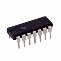
PIC16F684-E/P Microchip Technology, PIC16F684-E/P Datasheet - Page 158

PIC16F684-E/P
Manufacturer Part Number
PIC16F684-E/P
Description
IC PIC MCU FLASH 2KX14 14DIP
Manufacturer
Microchip Technology
Series
PIC® 16Fr
Datasheets
1.PIC16F616T-ISL.pdf
(8 pages)
2.PIC16F688T-ISL.pdf
(688 pages)
3.PIC16F684-ISL.pdf
(4 pages)
4.PIC16F684-ISL.pdf
(192 pages)
5.PIC16F684-ISL.pdf
(6 pages)
6.PIC16F684-IST.pdf
(164 pages)
Specifications of PIC16F684-E/P
Program Memory Type
FLASH
Program Memory Size
3.5KB (2K x 14)
Package / Case
14-DIP (0.300", 7.62mm)
Core Processor
PIC
Core Size
8-Bit
Speed
20MHz
Peripherals
Brown-out Detect/Reset, POR, PWM, WDT
Number Of I /o
12
Eeprom Size
256 x 8
Ram Size
128 x 8
Voltage - Supply (vcc/vdd)
2 V ~ 5.5 V
Data Converters
A/D 8x10b
Oscillator Type
Internal
Operating Temperature
-40°C ~ 125°C
Processor Series
PIC16F
Core
PIC
Data Bus Width
8 bit
Data Ram Size
128 B
Maximum Clock Frequency
20 MHz
Number Of Programmable I/os
12
Number Of Timers
3
Operating Supply Voltage
2 V to 5.5 V
Maximum Operating Temperature
+ 125 C
Mounting Style
Through Hole
3rd Party Development Tools
52715-96, 52716-328, 52717-734
Development Tools By Supplier
PG164130, DV164035, DV244005, DV164005, PG164120, ICE2000, DM163014, DM164120-4
Minimum Operating Temperature
- 40 C
On-chip Adc
8-ch x 10-bit
Lead Free Status / RoHS Status
Lead free / RoHS Compliant
For Use With
DM163029 - BOARD PICDEM FOR MECHATRONICSACICE0207 - MPLABICE 14P 300 MIL ADAPTER
Connectivity
-
Lead Free Status / Rohs Status
Lead free / RoHS Compliant
PIC16F684
D
Data EEPROM Memory
Data Memory......................................................................... 7
DC Characteristics
Demonstration Boards
Development Support ....................................................... 121
Device Overview ................................................................... 5
E
ECCP. See Enhanced Capture/Compare/PWM (ECCP)
ECCPAS Register ............................................................... 86
EEADR Register ................................................................. 71
EECON1 Register ............................................................... 72
EECON2 Register ............................................................... 72
EEDAT Register.................................................................. 71
EEPROM Data Memory
Electrical Specifications .................................................... 127
Enhanced Capture/Compare/PWM (ECCP) ....................... 75
DS41202C-page 156
Associated Registers .................................................. 74
Code Protection .................................................... 71, 74
Extended and Industrial ............................................ 134
Industrial and Extended ............................................ 129
PICDEM 1 ................................................................. 124
PICDEM 17 ............................................................... 125
PICDEM 18R ............................................................ 125
PICDEM 2 Plus ......................................................... 124
PICDEM 3 ................................................................. 124
PICDEM 4 ................................................................. 124
PICDEM LIN ............................................................. 125
PICDEM USB............................................................ 125
PICDEM.net Internet/Ethernet .................................. 124
Avoiding Spurious Write.............................................. 74
Reading....................................................................... 73
Write Verify ................................................................. 73
Writing ......................................................................... 73
Associated registers.................................................... 89
Associated registers w/ Capture/Compare/Timer1 ..... 77
Capture Mode ............................................................. 76
CCP1 Pin Configuration .............................................. 76
Compare Mode ........................................................... 77
Enhanced PWM Mode ................................................ 78
Prescaler............................................................. 76
CCP1 Pin Configuration...................................... 77
Software Interrupt Mode ..................................... 77
Special Event Trigger and A/D Conversions....... 77
Special Trigger Output ........................................ 77
Timer1 Mode Selection ....................................... 77
Auto-restart ......................................................... 87
Auto-shutdown .............................................. 85, 87
Direction Change in Full-Bridge Output Mode .... 83
Duty Cycle........................................................... 79
Effects of Reset................................................... 88
Example PWM Frequencies and Resolutions..... 79
Full-Bridge Application Example ......................... 83
Full-Bridge Mode................................................. 82
Half-Bridge Application Examples....................... 81
Half-Bridge Mode ................................................ 81
Operation in Power Managed Modes ................. 88
Operation with Fail-Safe Clock Monitor .............. 88
Output Configurations ......................................... 78
Output Relationships (Active-High and Active-Low)
Output Relationships Diagram ............................ 80
Period.................................................................. 79
Programmable Dead Band Delay ....................... 85
80
Preliminary
Errata .................................................................................... 3
Evaluation and Programming Tools.................................. 125
F
Fail-Safe Clock Monitor ...................................................... 27
Firmware Instructions ....................................................... 111
Fuses. See Configuration Bits
G
General Purpose Register File ............................................. 8
I
ID Locations...................................................................... 108
In-Circuit Debugger........................................................... 109
In-Circuit Serial Programming (ICSP)............................... 108
Indirect Addressing, INDF and FSR registers..................... 17
Instruction Format............................................................. 111
Instruction Set................................................................... 111
INTCON Register................................................................ 13
Internal Oscillator Block
Specifications ........................................................... 143
Timer Resources ........................................................ 75
Fail-Safe Mode ........................................................... 27
Reset and Wake-up from Sleep.................................. 28
ADDLW..................................................................... 113
ADDWF..................................................................... 113
ANDLW..................................................................... 113
ANDWF..................................................................... 113
BCF .......................................................................... 113
BSF........................................................................... 113
BTFSC ...................................................................... 113
BTFSS ...................................................................... 114
CALL......................................................................... 114
CLRF ........................................................................ 114
CLRW ....................................................................... 114
CLRWDT .................................................................. 114
COMF ....................................................................... 114
DECF ........................................................................ 114
DECFSZ ................................................................... 115
GOTO ....................................................................... 115
INCF ......................................................................... 115
INCFSZ..................................................................... 115
IORLW ...................................................................... 115
IORWF...................................................................... 115
MOVF ....................................................................... 116
MOVLW .................................................................... 116
MOVWF .................................................................... 116
NOP .......................................................................... 116
RETFIE ..................................................................... 117
RETLW ..................................................................... 117
RETURN................................................................... 117
RLF ........................................................................... 118
RRF .......................................................................... 118
SLEEP ...................................................................... 118
SUBLW ..................................................................... 118
SUBWF..................................................................... 119
SWAPF ..................................................................... 119
XORLW .................................................................... 119
XORWF .................................................................... 119
Summary Table ........................................................ 112
INTOSC
Setup for Operation ............................................ 88
Shoot-through Current ........................................ 85
Start-up Considerations ...................................... 87
TMR2 to PR2 Match ........................................... 53
Specifications ................................................... 138
2004 Microchip Technology Inc.


