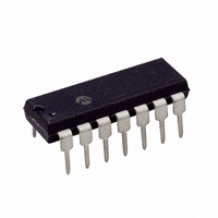
PIC16F684-E/P Microchip Technology, PIC16F684-E/P Datasheet - Page 159

PIC16F684-E/P
Manufacturer Part Number
PIC16F684-E/P
Description
IC PIC MCU FLASH 2KX14 14DIP
Manufacturer
Microchip Technology
Series
PIC® 16Fr
Datasheets
1.PIC16F616T-ISL.pdf
(8 pages)
2.PIC16F688T-ISL.pdf
(688 pages)
3.PIC16F684-ISL.pdf
(4 pages)
4.PIC16F684-ISL.pdf
(192 pages)
5.PIC16F684-ISL.pdf
(6 pages)
6.PIC16F684-IST.pdf
(164 pages)
Specifications of PIC16F684-E/P
Program Memory Type
FLASH
Program Memory Size
3.5KB (2K x 14)
Package / Case
14-DIP (0.300", 7.62mm)
Core Processor
PIC
Core Size
8-Bit
Speed
20MHz
Peripherals
Brown-out Detect/Reset, POR, PWM, WDT
Number Of I /o
12
Eeprom Size
256 x 8
Ram Size
128 x 8
Voltage - Supply (vcc/vdd)
2 V ~ 5.5 V
Data Converters
A/D 8x10b
Oscillator Type
Internal
Operating Temperature
-40°C ~ 125°C
Processor Series
PIC16F
Core
PIC
Data Bus Width
8 bit
Data Ram Size
128 B
Maximum Clock Frequency
20 MHz
Number Of Programmable I/os
12
Number Of Timers
3
Operating Supply Voltage
2 V to 5.5 V
Maximum Operating Temperature
+ 125 C
Mounting Style
Through Hole
3rd Party Development Tools
52715-96, 52716-328, 52717-734
Development Tools By Supplier
PG164130, DV164035, DV244005, DV164005, PG164120, ICE2000, DM163014, DM164120-4
Minimum Operating Temperature
- 40 C
On-chip Adc
8-ch x 10-bit
Lead Free Status / RoHS Status
Lead free / RoHS Compliant
For Use With
DM163029 - BOARD PICDEM FOR MECHATRONICSACICE0207 - MPLABICE 14P 300 MIL ADAPTER
Connectivity
-
Lead Free Status / Rohs Status
Lead free / RoHS Compliant
Internal Sampling Switch (R
Interrupts ........................................................................... 101
INTOSC Specifications ..................................................... 138
IOCA Register ..................................................................... 33
L
Load Conditions ................................................................ 136
M
MCLR .................................................................................. 95
Memory Organization............................................................ 7
Migrating from other PICmicro Devices ............................ 153
MPLAB ASM30 Assembler, Linker, Librarian ................... 122
MPLAB ICD 2 In-Circuit Debugger ................................... 123
MPLAB ICE 2000 High-Performance Universal
MPLAB ICE 4000 High-Performance Universal
MPLAB Integrated Development Environment Software .. 121
MPLAB PM3 Device Programmer .................................... 123
MPLINK Object Linker/MPLIB Object Librarian ................ 122
O
OPCODE Field Descriptions ............................................. 111
OPTION_REG Register ...................................................... 12
OSCCON Register .............................................................. 29
Oscillator
Oscillator Configurations ..................................................... 19
Oscillator Specifications .................................................... 137
Oscillator Start-up Timer (OST)
Oscillator Switching
P
P1A/P1B/P1C/P1D.See Enhanced
Packaging ......................................................................... 149
PCL and PCLATH ............................................................... 17
PCON Register ................................................................... 97
PICkit 1 Flash Starter Kit................................................... 125
PICSTART Plus Development Programmer ..................... 124
2004 Microchip Technology Inc.
A/D .............................................................................. 67
Associated Registers ................................................ 103
Capture ....................................................................... 76
Comparators ............................................................... 59
Compare ..................................................................... 77
Context Saving.......................................................... 104
Data EEPROM Memory Write .................................... 72
Interrupt-on-Change.................................................... 33
PORTA Interrupt-on-Change .................................... 102
RA2/INT .................................................................... 101
TMR0 ........................................................................ 102
TMR1 .......................................................................... 50
TMR2 to PR2 Match ................................................... 54
TMR2 to PR2 Match (PWM) ....................................... 53
Internal ........................................................................ 95
Data .............................................................................. 7
Data EEPROM Memory.............................................. 71
Program ........................................................................ 7
Associated registers.................................................... 29
Specifications............................................................ 141
Fail-Safe Clock Monitor............................................... 27
Two-Speed Clock Start-up.......................................... 25
Capture/Compare/PWM (ECCP) ................................ 78
Marking ..................................................................... 149
PDIP Details.............................................................. 150
Computed GOTO........................................................ 17
Stack ........................................................................... 17
In-Circuit Emulator ................................................... 123
In-Circuit Emulator ................................................... 123
SS
) Impedance ........................ 68
Preliminary
PIE1 Register ..................................................................... 14
Pin Diagram .......................................................................... 2
Pinout Descriptions
PIR1 Register ..................................................................... 15
PORTA ............................................................................... 31
PORTC ............................................................................... 40
Power-Down Mode (Sleep)............................................... 107
Power-on Reset (POR)....................................................... 95
Power-up Timer (PWRT) .................................................... 96
Precision Internal Oscillator Parameters .......................... 138
Prescaler
PRO MATE II Universal Device Programmer ................... 123
Product Identification ........................................................ 161
Program Memory .................................................................. 7
Programming, Device Instructions.................................... 111
PWM Mode. See Enhanced Capture/Compare/PWM ........ 78
PWM1CON Register........................................................... 85
R
Read-Modify-Write Operations ......................................... 111
Registers
PIC16F684 ................................................................... 6
Additional Pin Functions ............................................. 31
Associated registers ................................................... 39
Pin Descriptions and Diagrams .................................. 36
RA0............................................................................. 36
RA1............................................................................. 36
RA2............................................................................. 37
RA3............................................................................. 37
RA4............................................................................. 38
RA5............................................................................. 38
Specifications ........................................................... 139
Associated Registers.................................................. 29
Associated registers ................................................... 43
P1A/P1B/P1C/P1D.See Enhanced
Specifications ........................................................... 139
Specifications ........................................................... 141
Shared WDT/Timer0................................................... 47
Switching Prescaler Assignment ................................ 47
Map and Stack.............................................................. 7
ADCON0 (A/D Control 0)............................................ 66
ADCON1 (A/D Control 1)............................................ 66
ANSEL (Analog Select) .............................................. 65
CALIB (Calibration Word) ........................................... 93
CCP1CON (Enhanced CCP Operation) ..................... 75
CCPR1H..................................................................... 75
CCPR1L ..................................................................... 75
CMCON0 (Comparator Control 0) .............................. 55
CMCON1 (Comparator Control 1) .............................. 59
CONFIG (Configuration Word) ................................... 92
Data Memory Map ........................................................ 8
ECCPAS (Enhanced CCP Auto-shutdown Control) ... 86
EEADR (EEPROM Address) ...................................... 71
EECON1 (EEPROM Control 1) .................................. 72
EECON2 (EEPROM Control 2) .................................. 72
EEDAT (EEPROM Data) ............................................ 71
INTCON (Interrupt Control) ........................................ 13
IOCA (Interrupt-on-change PORTA) .......................... 33
OPTION_REG ............................................................ 46
OPTION_REG (Option) .............................................. 12
OSCCON (Oscillator Control)..................................... 29
PCON (Power Control) ............................................... 97
Interrupt-on-Change ........................................... 33
Ultra Low-Power Wake-up............................ 31, 34
Weak Pull-up ...................................................... 31
Capture/Compare/PWM (ECCP)........................ 40
PIC16F684
DS41202C-page 157


