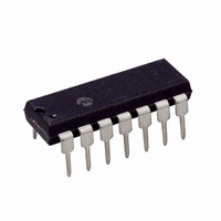
PIC16F684-E/P Microchip Technology, PIC16F684-E/P Datasheet - Page 36

PIC16F684-E/P
Manufacturer Part Number
PIC16F684-E/P
Description
IC PIC MCU FLASH 2KX14 14DIP
Manufacturer
Microchip Technology
Series
PIC® 16Fr
Datasheets
1.PIC16F616T-ISL.pdf
(8 pages)
2.PIC16F688T-ISL.pdf
(688 pages)
3.PIC16F684-ISL.pdf
(4 pages)
4.PIC16F684-ISL.pdf
(192 pages)
5.PIC16F684-ISL.pdf
(6 pages)
6.PIC16F684-IST.pdf
(164 pages)
Specifications of PIC16F684-E/P
Program Memory Type
FLASH
Program Memory Size
3.5KB (2K x 14)
Package / Case
14-DIP (0.300", 7.62mm)
Core Processor
PIC
Core Size
8-Bit
Speed
20MHz
Peripherals
Brown-out Detect/Reset, POR, PWM, WDT
Number Of I /o
12
Eeprom Size
256 x 8
Ram Size
128 x 8
Voltage - Supply (vcc/vdd)
2 V ~ 5.5 V
Data Converters
A/D 8x10b
Oscillator Type
Internal
Operating Temperature
-40°C ~ 125°C
Processor Series
PIC16F
Core
PIC
Data Bus Width
8 bit
Data Ram Size
128 B
Maximum Clock Frequency
20 MHz
Number Of Programmable I/os
12
Number Of Timers
3
Operating Supply Voltage
2 V to 5.5 V
Maximum Operating Temperature
+ 125 C
Mounting Style
Through Hole
3rd Party Development Tools
52715-96, 52716-328, 52717-734
Development Tools By Supplier
PG164130, DV164035, DV244005, DV164005, PG164120, ICE2000, DM163014, DM164120-4
Minimum Operating Temperature
- 40 C
On-chip Adc
8-ch x 10-bit
Lead Free Status / RoHS Status
Lead free / RoHS Compliant
For Use With
DM163029 - BOARD PICDEM FOR MECHATRONICSACICE0207 - MPLABICE 14P 300 MIL ADAPTER
Connectivity
-
Lead Free Status / Rohs Status
Lead free / RoHS Compliant
PIC16F684
4.2.3
The Ultra Low-power Wake-up (ULPWU) on RA0
allows a slow falling voltage to generate an interrupt-
on-change on RA0 without excess current consump-
tion. The mode is selected by setting the ULPWUE bit
(PCON<5>). This enables a small current sink which
can be used to discharge a capacitor on RA0.
To use this feature, the RA0 pin is configured to output
‘1’ to charge the capacitor, interrupt-on-change for RA0
is enabled, and RA0 is configured as an input. The
ULPWUE bit is set to begin the discharge and a SLEEP
instruction is performed. When the voltage on RA0 drops
below V
the device to wake-up. Depending on the state of the
GIE bit (INTCON<7>), the device will either jump to the
interrupt vector (0004h) or execute the next instruction
when the interrupt event occurs. See Section 4.2.2
“Interrupt-on-change” and Section 12.4.3 “PORTA
Interrupt” for more information.
This feature provides a low-power technique for
periodically waking up the device from Sleep. The
time-out is dependent on the discharge time of the RC
circuit on RA0. See Example 4-2 for initializing the
Ultra Low-Power Wake-up module.
DS41202C-page 34
IL
, an interrupt will be generated which will cause
ULTRA LOW-POWER WAKE-UP
Preliminary
The series resistor provides overcurrent protection for
the RA0 pin and can allow for software calibration of
the time-out (see Figure 4-1). A timer can be used to
measure the charge time and discharge time of the
capacitor. The charge time can then be adjusted to pro-
vide the desired interrupt delay. This technique will
compensate for the affects of temperature, voltage and
component accuracy. The Ultra Low-power Wake-up
peripheral can also be configured as a simple
Programmable Low Voltage Detect or temperature
sensor.
EXAMPLE 4-2:
BCF
BSF
MOVLW
MOVWF
BSF
BCF
BCF
CALL
BSF
BSF
BSF
MOVLW
MOVWF
SLEEP
Note:
STATUS,RP0
PORTA,0
H’7’
CMCON0
STATUS,RP0
ANSEL,0
TRISA,0
CapDelay
PCON,ULPWUE ;Enable ULP Wake-up
IOCA,0
TRISA,0
B’10001000’ ;Enable interrupt
INTCON
For more information, refer to AN879,
“Using the Microchip Ultra Low-Power
Wake-up
(DS00879).
ULTRA LOW-POWER
WAKE-UP INITIALIZATION
Module”
2004 Microchip Technology Inc.
;Bank 0
;Set RA0 data latch
;Turn off
;comparators
;Bank 1
;RA0 to digital I/O
;Output high to
; charge capacitor
;Select RA0 IOC
;RA0 to input
; and clear flag
;Wait for IOC
Application
Note


