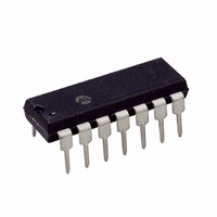
PIC16F684-E/P Microchip Technology, PIC16F684-E/P Datasheet - Page 160

PIC16F684-E/P
Manufacturer Part Number
PIC16F684-E/P
Description
IC PIC MCU FLASH 2KX14 14DIP
Manufacturer
Microchip Technology
Series
PIC® 16Fr
Datasheets
1.PIC16F616T-ISL.pdf
(8 pages)
2.PIC16F688T-ISL.pdf
(688 pages)
3.PIC16F684-ISL.pdf
(4 pages)
4.PIC16F684-ISL.pdf
(192 pages)
5.PIC16F684-ISL.pdf
(6 pages)
6.PIC16F684-IST.pdf
(164 pages)
Specifications of PIC16F684-E/P
Program Memory Type
FLASH
Program Memory Size
3.5KB (2K x 14)
Package / Case
14-DIP (0.300", 7.62mm)
Core Processor
PIC
Core Size
8-Bit
Speed
20MHz
Peripherals
Brown-out Detect/Reset, POR, PWM, WDT
Number Of I /o
12
Eeprom Size
256 x 8
Ram Size
128 x 8
Voltage - Supply (vcc/vdd)
2 V ~ 5.5 V
Data Converters
A/D 8x10b
Oscillator Type
Internal
Operating Temperature
-40°C ~ 125°C
Processor Series
PIC16F
Core
PIC
Data Bus Width
8 bit
Data Ram Size
128 B
Maximum Clock Frequency
20 MHz
Number Of Programmable I/os
12
Number Of Timers
3
Operating Supply Voltage
2 V to 5.5 V
Maximum Operating Temperature
+ 125 C
Mounting Style
Through Hole
3rd Party Development Tools
52715-96, 52716-328, 52717-734
Development Tools By Supplier
PG164130, DV164035, DV244005, DV164005, PG164120, ICE2000, DM163014, DM164120-4
Minimum Operating Temperature
- 40 C
On-chip Adc
8-ch x 10-bit
Lead Free Status / RoHS Status
Lead free / RoHS Compliant
For Use With
DM163029 - BOARD PICDEM FOR MECHATRONICSACICE0207 - MPLABICE 14P 300 MIL ADAPTER
Connectivity
-
Lead Free Status / Rohs Status
Lead free / RoHS Compliant
PIC16F684
Reset................................................................................... 94
Revision History ................................................................ 153
S
Shoot-through Current ........................................................ 85
Software Simulator (MPLAB SIM)..................................... 122
Software Simulator (MPLAB SIM30)................................. 122
Special Event Trigger.......................................................... 69
Special Function Registers ................................................... 8
Status Register.................................................................... 11
T
Time-out Sequence............................................................. 97
Timer0 ................................................................................. 45
Timer1 ................................................................................. 49
Timer2 ................................................................................. 53
Timing Diagrams
DS41202C-page 158
PIE1 (Peripheral Interrupt Enable 1) ........................... 14
PIR1 (Peripheral Interrupt Register 1) ........................ 15
PORTA........................................................................ 31
PORTC ....................................................................... 43
PWM1CON (Enhanced PWM Configuration) ............. 85
Reset Values............................................................... 99
Reset Values (special registers) ............................... 100
Special Function Registers ........................................... 8
Special Register Summary ......................................... 10
Status .......................................................................... 11
T1CON (Timer1 Control)............................................. 51
T2CON (Timer2 Control)............................................. 53
TRISA (Tri-state PORTA) ........................................... 32
TRISC (Tri-state PORTC) ........................................... 43
VRCON (Voltage Reference Control) ......................... 62
WDTCON (Watchdog Timer Control)........................ 106
WPUA (Weak Pull-up PORTA) ................................... 32
Associated Registers .................................................. 47
External Clock ............................................................. 46
Interrupt....................................................................... 45
Operation .................................................................... 45
Specifications ............................................................ 142
T0CKI .......................................................................... 46
Associated registers.................................................... 52
Asynchronous Counter Mode ..................................... 52
Interrupt....................................................................... 50
Modes of Operations................................................... 50
Operation During Sleep .............................................. 52
Oscillator ..................................................................... 52
Prescaler ..................................................................... 50
Specifications ............................................................ 142
Timer1 Gate
TMR1H Register ......................................................... 49
TMR1L Register .......................................................... 49
Associated Registers .................................................. 54
Operation .................................................................... 53
Postscaler ................................................................... 53
PR2 Register............................................................... 53
Prescaler ..................................................................... 53
TMR2 Register ............................................................ 53
TMR2 to PR2 Match Interrupt ............................... 53, 54
A/D Conversion ......................................................... 145
A/D Conversion (Sleep Mode) .................................. 146
Brown-out Detect (BOD) ........................................... 140
Brown-out Detect Situations ....................................... 96
Reading and Writing ........................................... 52
Inverting Gate ..................................................... 50
Selecting Source........................................... 50, 59
Synchronizing C2OUT w/ Timer1 ....................... 59
Preliminary
Timing Parameter Symbology .......................................... 136
TRISA Register................................................................... 32
TRISC Register................................................................... 43
Two-Speed Clock Start-up Mode........................................ 25
U
Ultra Low-Power Wake-up............................................ 31, 34
Ultra Low-power Wake-up .................................................... 6
V
Voltage Reference. See Comparator
VRCON Register ................................................................ 62
V
W
Wake-up Using Interrupts ................................................. 107
Watchdog Timer (WDT).................................................... 105
WDTCON Register ........................................................... 106
WPUA Register................................................................... 32
WWW, On-Line Support ....................................................... 3
REF
CLKOUT and I/O ...................................................... 138
Comparator Output ..................................................... 56
Enhanced Capture/Compare/PWM (ECCP)............. 143
External Clock........................................................... 137
Fail-Safe Clock Monitor (FSCM)................................. 28
Full-Bridge PWM Output............................................. 82
Half-Bridge PWM Output ............................................ 81
INT Pin Interrupt ....................................................... 103
PWM Auto-shutdown
PWM Direction Change .............................................. 84
PWM Direction Change at Near 100% Duty Cycle..... 84
PWM Output (Active-High) ......................................... 80
PWM Output (Active-Low) .......................................... 80
Reset, WDT, OST and Power-up Timer ................... 140
Time-out Sequence
Timer0 and Timer1 External Clock ........................... 142
Timer1 Incrementing Edge ......................................... 50
Two Speed Start-up.................................................... 26
Wake-up from Interrupt............................................. 108
Voltage Reference (CV
Associated registers ................................................. 106
Clock Source ............................................................ 105
Modes ....................................................................... 105
Period ....................................................................... 105
Specifications ........................................................... 141
. S
EE
Auto-restart Disabled.......................................... 87
Auto-restart Enabled........................................... 87
Case 1 ................................................................ 98
Case 2 ................................................................ 98
Case 3 ................................................................ 98
A/D Reference Voltage
2004 Microchip Technology Inc.
REF
)


