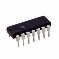
PIC16F684-E/P Microchip Technology, PIC16F684-E/P Datasheet - Page 23

PIC16F684-E/P
Manufacturer Part Number
PIC16F684-E/P
Description
IC PIC MCU FLASH 2KX14 14DIP
Manufacturer
Microchip Technology
Series
PIC® 16Fr
Datasheets
1.PIC16F616T-ISL.pdf
(8 pages)
2.PIC16F688T-ISL.pdf
(688 pages)
3.PIC16F684-ISL.pdf
(4 pages)
4.PIC16F684-ISL.pdf
(192 pages)
5.PIC16F684-ISL.pdf
(6 pages)
6.PIC16F684-IST.pdf
(164 pages)
Specifications of PIC16F684-E/P
Program Memory Type
FLASH
Program Memory Size
3.5KB (2K x 14)
Package / Case
14-DIP (0.300", 7.62mm)
Core Processor
PIC
Core Size
8-Bit
Speed
20MHz
Peripherals
Brown-out Detect/Reset, POR, PWM, WDT
Number Of I /o
12
Eeprom Size
256 x 8
Ram Size
128 x 8
Voltage - Supply (vcc/vdd)
2 V ~ 5.5 V
Data Converters
A/D 8x10b
Oscillator Type
Internal
Operating Temperature
-40°C ~ 125°C
Processor Series
PIC16F
Core
PIC
Data Bus Width
8 bit
Data Ram Size
128 B
Maximum Clock Frequency
20 MHz
Number Of Programmable I/os
12
Number Of Timers
3
Operating Supply Voltage
2 V to 5.5 V
Maximum Operating Temperature
+ 125 C
Mounting Style
Through Hole
3rd Party Development Tools
52715-96, 52716-328, 52717-734
Development Tools By Supplier
PG164130, DV164035, DV244005, DV164005, PG164120, ICE2000, DM163014, DM164120-4
Minimum Operating Temperature
- 40 C
On-chip Adc
8-ch x 10-bit
Lead Free Status / RoHS Status
Lead free / RoHS Compliant
For Use With
DM163029 - BOARD PICDEM FOR MECHATRONICSACICE0207 - MPLABICE 14P 300 MIL ADAPTER
Connectivity
-
Lead Free Status / Rohs Status
Lead free / RoHS Compliant
3.3.3
The LP, XT and HS modes support the use of quartz
crystal resonators or ceramic resonators connected to
the OSC1 and OSC2 pins (Figure 3-1). The mode
selects a low, medium or high gain setting of the
internal inverter-amplifier to support various resonator
types and speed.
LP Oscillator mode selects the lowest gain setting of
the internal inverter-amplifier. LP mode current con-
sumption is the least of the three modes. This mode is
best suited to drive resonators with a low drive level
specification, for example, tuning fork type crystals.
XT Oscillator mode selects the intermediate gain
setting of the internal inverter-amplifier. XT mode
current consumption is the medium of the three modes.
This mode is best suited to drive resonators with a
medium drive
low-frequency/AT-cut quartz crystal resonators.
HS Oscillator mode selects the highest gain setting of
the internal inverter-amplifier. HS mode current
consumption is the highest of the three modes. This
mode is best suited for resonators that require a high
drive setting, for example, high-frequency/AT-cut
quartz crystal resonators or ceramic resonators.
Figure 3-3 and Figure 3-4 show typical circuits for
quartz crystal and ceramic resonators, respectively.
FIGURE 3-3:
2004 Microchip Technology Inc.
Note 1: Quartz
Note 1: A series resistor (R
2: Always verify oscillator performance over
2: The value of R
C1
C2
LP, XT, HS MODES
according to type, package and manufac-
turer. The user should consult the manu-
facturer data sheets for specifications and
recommended application.
the V
expected for the application.
quartz crystals with low drive level.
mode selected (typically between 2 M
10 M
Quartz
Crystal
level specification,
R
DD
S (1)
.
OSC1
OSC2
and temperature range that is
crystal
QUARTZ CRYSTAL
OPERATION (LP, XT OR
HS MODE)
PIC16F684
F
varies with the Oscillator
R
S
F (2)
characteristics
) may be required for
for
Sleep
To Internal
Logic
example,
vary
to
Preliminary
FIGURE 3-4:
Note 1: A series resistor (R
C1
C2 Ceramic
2: The value of R
3: An additional parallel feedback resistor (R
Resonator
ceramic resonators with low drive level.
mode selected (typically between 2 M
10 M
may be required for proper ceramic resonator
operation (typical value 1 M ).
R
.
P (3)
R
OSC2
S (1)
OSC1
CERAMIC RESONATOR
OPERATION
(XT OR HS MODE)
PIC16F684
PIC16F684
F
varies with the Oscillator
R
S
F (2)
) may be required for
DS41202C-page 21
To Internal
Logic
Sleep
P
to
)


