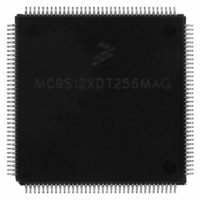
MC9S12XDT256MAG Freescale Semiconductor, MC9S12XDT256MAG Datasheet - Page 334

MC9S12XDT256MAG
Manufacturer Part Number
MC9S12XDT256MAG
Description
IC MCU 256K FLASH 144-LQFP
Manufacturer
Freescale Semiconductor
Series
HCS12r
Datasheet
1.MC9S12XD64CAA.pdf
(1348 pages)
Specifications of MC9S12XDT256MAG
Core Processor
HCS12X
Core Size
16-Bit
Speed
80MHz
Connectivity
CAN, EBI/EMI, I²C, IrDA, LIN, SCI, SPI
Peripherals
LVD, POR, PWM, WDT
Number Of I /o
119
Program Memory Size
256KB (256K x 8)
Program Memory Type
FLASH
Eeprom Size
4K x 8
Ram Size
16K x 8
Voltage - Supply (vcc/vdd)
2.35 V ~ 5.5 V
Data Converters
A/D 24x10b
Oscillator Type
External
Operating Temperature
-40°C ~ 125°C
Package / Case
144-LQFP
Processor Series
S12XD
Core
HCS12
Data Bus Width
16 bit
Data Ram Size
16 KB
Interface Type
CAN/I2C/SCI/SPI
Maximum Clock Frequency
40 MHz
Number Of Programmable I/os
119
Number Of Timers
12
Operating Supply Voltage
0 V to 5.5 V
Maximum Operating Temperature
+ 125 C
Mounting Style
SMD/SMT
3rd Party Development Tools
EWHCS12
Development Tools By Supplier
EVB9S12XDP512E
Minimum Operating Temperature
- 40 C
On-chip Adc
2 (24-ch x 10-bit)
Lead Free Status / RoHS Status
Lead free / RoHS Compliant
Available stocks
Company
Part Number
Manufacturer
Quantity
Price
Company:
Part Number:
MC9S12XDT256MAG
Manufacturer:
Freescale Semiconductor
Quantity:
10 000
- Current page: 334 of 1348
- Download datasheet (8Mb)
Chapter 7 Enhanced Capture Timer (S12ECT16B8CV2)
7.3.2.16
Read: Anytime
Write used in the flag clearing mechanism. Writing a one to the flag clears the flag. Writing a zero will not
affect the current status of the bit.
All bits reset to zero.
PAFLG indicates when interrupt conditions have occurred. The flags can be cleared via the normal flag
clearing mechanism (writing a one to the flag) or via the fast flag clearing mechanism (Reference TFFCA
bit in
7.3.2.17
334
PAOVF
Reset
Reset
Field
PAIF
1
0
Section 7.3.2.6, “Timer System Control Register 1
W
W
R
R
PACNT7(15) PACNT6(14) PACNT5(13) PACNT4(12) PACNT3(11) PACNT2(10)
Pulse Accumulator A Overflow Flag — Set when the 16-bit pulse accumulator A overflows from 0xFFFF to
0x0000, or when 8-bit pulse accumulator 3 (PAC3) overflows from 0x00FF to 0x0000.
When PACMX = 1, PAOVF bit can also be set if 8-bit pulse accumulator 3 (PAC3) reaches 0x00FF followed by
an active edge on PT3.
Pulse Accumulator Input edge Flag — Set when the selected edge is detected at the PT7 input pin. In event
mode the event edge triggers PAIF and in gated time accumulation mode the trailing edge of the gate signal at
the PT7 input pin triggers PAIF.
Pulse Accumulator A Flag Register (PAFLG)
Pulse Accumulators Count Registers (PACN3 and PACN2)
0
0
0
7
7
When TFFCA = 1, the flags cannot be cleared via the normal flag clearing
mechanism (writing a one to the flag). Reference
System Control Register 1
= Unimplemented or Reserved
Figure 7-37. Pulse Accumulators Count Register 3 (PACN3)
Figure 7-36. Pulse Accumulator A Flag Register (PAFLG)
0
0
0
6
6
Table 7-21. PAFLG Field Descriptions
MC9S12XDP512 Data Sheet, Rev. 2.21
0
0
0
5
5
(TSCR1)”.
NOTE
0
0
0
4
4
Description
(TSCR1)”).
0
0
0
3
3
Section 7.3.2.6, “Timer
0
0
0
2
2
PACNT1(9)
PAOVF
Freescale Semiconductor
0
0
1
1
PACNT0(8)
PAIF
0
0
0
0
Related parts for MC9S12XDT256MAG
Image
Part Number
Description
Manufacturer
Datasheet
Request
R

Part Number:
Description:
16-BIT MICROPROCESSOR FAMILY
Manufacturer:
FREESCALE [Freescale Semiconductor, Inc]
Datasheet:
Part Number:
Description:
Manufacturer:
Freescale Semiconductor, Inc
Datasheet:
Part Number:
Description:
Manufacturer:
Freescale Semiconductor, Inc
Datasheet:
Part Number:
Description:
Manufacturer:
Freescale Semiconductor, Inc
Datasheet:
Part Number:
Description:
Manufacturer:
Freescale Semiconductor, Inc
Datasheet:
Part Number:
Description:
Manufacturer:
Freescale Semiconductor, Inc
Datasheet:
Part Number:
Description:
Manufacturer:
Freescale Semiconductor, Inc
Datasheet:
Part Number:
Description:
Manufacturer:
Freescale Semiconductor, Inc
Datasheet:
Part Number:
Description:
Manufacturer:
Freescale Semiconductor, Inc
Datasheet:
Part Number:
Description:
Manufacturer:
Freescale Semiconductor, Inc
Datasheet:
Part Number:
Description:
Manufacturer:
Freescale Semiconductor, Inc
Datasheet:
Part Number:
Description:
Manufacturer:
Freescale Semiconductor, Inc
Datasheet:
Part Number:
Description:
Manufacturer:
Freescale Semiconductor, Inc
Datasheet:
Part Number:
Description:
Manufacturer:
Freescale Semiconductor, Inc
Datasheet:
Part Number:
Description:
Manufacturer:
Freescale Semiconductor, Inc
Datasheet:


