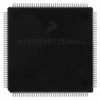
MC9S12XDT256MAG Freescale Semiconductor, MC9S12XDT256MAG Datasheet - Page 762

MC9S12XDT256MAG
Manufacturer Part Number
MC9S12XDT256MAG
Description
IC MCU 256K FLASH 144-LQFP
Manufacturer
Freescale Semiconductor
Series
HCS12r
Datasheet
1.MC9S12XD64CAA.pdf
(1348 pages)
Specifications of MC9S12XDT256MAG
Core Processor
HCS12X
Core Size
16-Bit
Speed
80MHz
Connectivity
CAN, EBI/EMI, I²C, IrDA, LIN, SCI, SPI
Peripherals
LVD, POR, PWM, WDT
Number Of I /o
119
Program Memory Size
256KB (256K x 8)
Program Memory Type
FLASH
Eeprom Size
4K x 8
Ram Size
16K x 8
Voltage - Supply (vcc/vdd)
2.35 V ~ 5.5 V
Data Converters
A/D 24x10b
Oscillator Type
External
Operating Temperature
-40°C ~ 125°C
Package / Case
144-LQFP
Processor Series
S12XD
Core
HCS12
Data Bus Width
16 bit
Data Ram Size
16 KB
Interface Type
CAN/I2C/SCI/SPI
Maximum Clock Frequency
40 MHz
Number Of Programmable I/os
119
Number Of Timers
12
Operating Supply Voltage
0 V to 5.5 V
Maximum Operating Temperature
+ 125 C
Mounting Style
SMD/SMT
3rd Party Development Tools
EWHCS12
Development Tools By Supplier
EVB9S12XDP512E
Minimum Operating Temperature
- 40 C
On-chip Adc
2 (24-ch x 10-bit)
Lead Free Status / RoHS Status
Lead free / RoHS Compliant
Available stocks
Company
Part Number
Manufacturer
Quantity
Price
Company:
Part Number:
MC9S12XDT256MAG
Manufacturer:
Freescale Semiconductor
Quantity:
10 000
- Current page: 762 of 1348
- Download datasheet (8Mb)
Chapter 20 S12X Debug (S12XDBGV3) Module
Table 20-28
tagged operations since the trigger occurs based on the tagged opcode reaching the execution stage of the
instruction queue. Thus these bits are ignored if tagged triggering is selected.
764
COMPE
Field
RWE
BRK
SRC
RW
4
3
2
1
0
shows the effect for RWE and RW on the comparison conditions. These bits are not useful for
Break — This bit controls whether a comparator match terminates a debug session immediately,
independent of state sequencer state. To generate an immediate breakpoint the module breakpoints must be
enabled using the DBGC1 bits DBGBRK[1:0].
0 The debug session termination is dependent upon the state sequencer and trigger conditions.
1 A match on this channel terminates the debug session immediately; breakpoints if active are generated,
Read/Write Comparator Value Bit — The RW bit controls whether read or write is used in compare for the
associated comparator. The RW bit is not used if RWE = 0.
0 Write cycle will be matched
1 Read cycle will be matched
Read/Write Enable Bit — The RWE bit controls whether read or write comparison is enabled for the
associated comparator. This bit is not useful for tagged operations.
0 Read/Write is not used in comparison
1 Read/Write is used in comparison
Determines mapping of comparator to S12XCPU or XGATE
0 The comparator is mapped to S12XCPU buses
1 The comparator is mapped to XGATE address and data buses
Determines if comparator is enabled
0 The comparator is not enabled
1 The comparator is enabled for state sequence triggers or tag generation
RWE Bit
tracing, if active, is terminated and the module disarmed.
0
0
1
1
1
1
Table 20-27. DBGXCTL Field Descriptions (continued)
Table 20-28. Read or Write Comparison Logic Table
RW Bit
x
x
0
0
1
1
MC9S12XDP512 Data Sheet, Rev. 2.21
RW Signal
0
1
0
1
0
1
Description
RW not used in comparison
RW not used in comparison
Write data bus
Read data bus
Comment
No match
No match
Freescale Semiconductor
Related parts for MC9S12XDT256MAG
Image
Part Number
Description
Manufacturer
Datasheet
Request
R

Part Number:
Description:
16-BIT MICROPROCESSOR FAMILY
Manufacturer:
FREESCALE [Freescale Semiconductor, Inc]
Datasheet:
Part Number:
Description:
Manufacturer:
Freescale Semiconductor, Inc
Datasheet:
Part Number:
Description:
Manufacturer:
Freescale Semiconductor, Inc
Datasheet:
Part Number:
Description:
Manufacturer:
Freescale Semiconductor, Inc
Datasheet:
Part Number:
Description:
Manufacturer:
Freescale Semiconductor, Inc
Datasheet:
Part Number:
Description:
Manufacturer:
Freescale Semiconductor, Inc
Datasheet:
Part Number:
Description:
Manufacturer:
Freescale Semiconductor, Inc
Datasheet:
Part Number:
Description:
Manufacturer:
Freescale Semiconductor, Inc
Datasheet:
Part Number:
Description:
Manufacturer:
Freescale Semiconductor, Inc
Datasheet:
Part Number:
Description:
Manufacturer:
Freescale Semiconductor, Inc
Datasheet:
Part Number:
Description:
Manufacturer:
Freescale Semiconductor, Inc
Datasheet:
Part Number:
Description:
Manufacturer:
Freescale Semiconductor, Inc
Datasheet:
Part Number:
Description:
Manufacturer:
Freescale Semiconductor, Inc
Datasheet:
Part Number:
Description:
Manufacturer:
Freescale Semiconductor, Inc
Datasheet:
Part Number:
Description:
Manufacturer:
Freescale Semiconductor, Inc
Datasheet:


