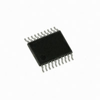
C8051F537-IT Silicon Laboratories Inc, C8051F537-IT Datasheet - Page 5

C8051F537-IT
Manufacturer Part Number
C8051F537-IT
Description
IC 8051 MCU 2K FLASH 20TSSOP
Manufacturer
Silicon Laboratories Inc
Series
C8051F53xr
Specifications of C8051F537-IT
Core Processor
8051
Core Size
8-Bit
Speed
25MHz
Connectivity
SPI, UART/USART
Peripherals
Brown-out Detect/Reset, POR, PWM, Temp Sensor, WDT
Number Of I /o
16
Program Memory Size
2KB (2K x 8)
Program Memory Type
FLASH
Ram Size
256 x 8
Voltage - Supply (vcc/vdd)
2 V ~ 5.25 V
Data Converters
A/D 16x12b
Oscillator Type
Internal
Operating Temperature
-40°C ~ 125°C
Package / Case
20-TSSOP
Lead Free Status / RoHS Status
Lead free / RoHS Compliant
Eeprom Size
-
Other names
336-1401
Available stocks
Company
Part Number
Manufacturer
Quantity
Price
Company:
Part Number:
C8051F537-IT
Manufacturer:
Silicon Labs
Quantity:
135
15. UART0 ................................................................................................................... 143
16. Enhanced Serial Peripheral Interface (SPI0) ..................................................... 150
17. LIN (C8051F520/0A/3/3A/6/6A and C8051F530/0A/3/3A/6/6A) .......................... 163
18. Timers ................................................................................................................... 181
19. Programmable Counter Array (PCA0)................................................................ 194
14.3. System Clock Selection................................................................................. 142
15.1. Enhanced Baud Rate Generation.................................................................. 144
15.2. Operational Modes ........................................................................................ 145
15.3. Multiprocessor Communications ................................................................... 147
16.1. Signal Descriptions........................................................................................ 151
16.2. SPI0 Master Mode Operation ........................................................................ 152
16.3. SPI0 Slave Mode Operation .......................................................................... 153
16.4. SPI0 Interrupt Sources .................................................................................. 154
16.5. Serial Clock Timing........................................................................................ 155
16.6. SPI Special Function Registers ..................................................................... 155
17.1. Software Interface with the LIN Peripheral .................................................... 164
17.2. LIN Interface Setup and Operation................................................................ 164
17.3. LIN Master Mode Operation .......................................................................... 168
17.4. LIN Slave Mode Operation ............................................................................ 169
17.5. Sleep Mode and Wake-Up ............................................................................ 170
17.6. Error Detection and Handling ........................................................................ 170
17.7. LIN Registers................................................................................................. 171
18.1. Timer 0 and Timer 1 ...................................................................................... 181
18.2. Timer 2 .......................................................................................................... 189
14.2.3. External RC Example............................................................................ 140
14.2.4. External Capacitor Example.................................................................. 140
15.2.1. 8-Bit UART ............................................................................................ 145
15.2.2. 9-Bit UART ............................................................................................ 146
16.1.1. Master Out, Slave In (MOSI)................................................................. 151
16.1.2. Master In, Slave Out (MISO)................................................................. 151
16.1.3. Serial Clock (SCK) ................................................................................ 151
16.1.4. Slave Select (NSS) ............................................................................... 151
17.2.1. Mode Definition ..................................................................................... 164
17.2.2. Baud Rate Options: Manual or Autobaud ............................................. 164
17.2.3. Baud Rate Calculations—Manual Mode ............................................... 164
17.2.4. Baud Rate Calculations—Automatic Mode ........................................... 167
17.7.1. LIN Direct Access SFR Registers Definition ......................................... 171
17.7.2. LIN Indirect Access SFR Registers Definition....................................... 173
18.1.1. Mode 0: 13-bit Counter/Timer ............................................................... 181
18.1.2. Mode 1: 16-bit Counter/Timer ............................................................... 183
18.1.3. Mode 2: 8-bit Counter/Timer with Auto-Reload..................................... 183
18.1.4. Mode 3: Two 8-bit Counter/Timers (Timer 0 Only)................................ 184
18.2.1. 16-bit Timer with Auto-Reload............................................................... 189
18.2.2. 8-bit Timers with Auto-Reload............................................................... 190
18.2.3. External Capture Mode ......................................................................... 191
C8051F52x/F52xA/F53x/F53xA
Rev. 1.3
5


