STEVAL-IPE010V1 STMicroelectronics, STEVAL-IPE010V1 Datasheet - Page 32
STEVAL-IPE010V1
Manufacturer Part Number
STEVAL-IPE010V1
Description
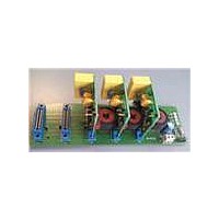
KIT DEMO ENERGY METER STPMC1/S1
Manufacturer
STMicroelectronics
Type
Other Power Managementr
Specifications of STEVAL-IPE010V1
Main Purpose
Power Management, Energy/Power Meter
Embedded
No
Utilized Ic / Part
STPMC1, STPMS1
Maximum Operating Temperature
+ 85 C
Product
Power Management Development Tools
Lead Free Status / RoHS Status
Lead free / RoHS Compliant
Secondary Attributes
-
Primary Attributes
-
Lead Free Status / Rohs Status
Lead free / RoHS Compliant
For Use With/related Products
STPMC1, STPMS1
Other names
497-10754


Theory of operation
Table 15.
9.10.3
9.10.4
32/77
DAR
DAN
DAR
DAS
DAS
DAT
DAT
Pin
Whatever the SYS bits setting (indicating phases presence and configuration), bit BSF is
always calculated, but it is valid only in cases SYS is 0, 1, 2 and 3. In fact in this case all the
three phase voltage signals (u
In cases SYS is 4, 5, 6, 7, only two or one voltage signal are available (u
the sequence cannot be checked. Bit BSF is always set in the status byte, but it must be
ignored.
In standalone application for SYS = 0, 1 or 2 (3-phase systems) bit BSF is available as
output on SDATD pin.
Pin description versus SYS configuration (u
current signals)
Phase active powers do not have the same sign (status bit BIF)
The 3-phase status bit BIF is produced from status bit SIGN of each phase. If bit SIGN is not
equal in all three phases (R, S and T), then bit BIF is set.
In a standalone application for SYS = 0, 1 or 2 (3-phase system) bit BIF is available as
output on SDATD pin.
Example 9: status bit BIF
EMI is detected
EMI tamper detection is enabled by configuring bits ENH = 1 and APL [1] = 1 (APL [1] sets
standalone application mode).
The DAH signal is checked to verify that:
●
●
where DC
If these condition are not verified the EMI tamper is detected.
u
u
u
i
i
i
i
0
N
R
S
T
R
S
T
SIGN
SIGN
SIGN
SIGN
its DC component does not exceed DC
its RMS value does not exceed the maximum value RMS
MAX
R
R
R
R
= 0, SIGN
= 1, SIGN
= 1, SIGN
= 0, SIGN
= RMS
u
u
u
i
i
i
1
-
R
S
T
R
S
T
MAX
S
S
S
S
= 0, SIGN
= 1, SIGN
= 0, SIGN
= 1, SIGN
= 2
u
u
u
i
i
i
2
-
R
S
T
R
S
T
16
R
Doc ID 15728 Rev 4
, u
with hysteresis.
S
T
T
T
T
, u
= 0
= 1
= 0
= 0
T
u
u
u
i
i
) are available and can be checked, as shown in 0.
3
-
R
-
T
R
S
T
BIF = 0
BIF = 0
BIF = 1
BIF = 1
SYS
MAX
X
/16
and i
u
u
i
i
4
-
-
-
S
T
S
T
X
represent the voltage and the
u
i
MAX
i
5
-
-
-
-
S
T
T
/16
S
and/or u
u
i
i
6
-
-
-
-
S
T
T
T
), so that
STPMC1
u
i
7
-
-
-
-
-
T
T
Related parts for STEVAL-IPE010V1
Image
Part Number
Description
Manufacturer
Datasheet
Request
R

Part Number:
Description:
BOARD DEMO TFT DISPLAY STR91
Manufacturer:
STMicroelectronics
Datasheet:

Part Number:
Description:
BOARD EVAL FOR MEMS SENSORS
Manufacturer:
STMicroelectronics
Datasheet:

Part Number:
Description:
KIT DEV STARTER ST10F276Z5
Manufacturer:
STMicroelectronics
Datasheet:

Part Number:
Description:
BOARD EVAL HDMI $ VIDEO SWITCH
Manufacturer:
STMicroelectronics
Datasheet:

Part Number:
Description:
BOARD DEMO ACCELEROMETER DIL24
Manufacturer:
STMicroelectronics
Datasheet:

Part Number:
Description:
BOARD STLM75/STDS75/ST72F651
Manufacturer:
STMicroelectronics
Datasheet:

Part Number:
Description:
EVAL BOARD 3AXIS MEMS ACCELLRMTR
Manufacturer:
STMicroelectronics
Datasheet:

Part Number:
Description:
BOARD EVAL 8BIT MICRO + TDE1708
Manufacturer:
STMicroelectronics
Datasheet:

Part Number:
Description:
EVAL BOARD A/D TS4657
Manufacturer:
STMicroelectronics
Datasheet:

Part Number:
Description:
BOARD ADAPTER 20DIP LIS3LV02DL
Manufacturer:
STMicroelectronics
Datasheet:
Part Number:
Description:
STMicroelectronics [RIPPLE-CARRY BINARY COUNTER/DIVIDERS]
Manufacturer:
STMicroelectronics
Datasheet:
Part Number:
Description:
STMicroelectronics [LIQUID-CRYSTAL DISPLAY DRIVERS]
Manufacturer:
STMicroelectronics
Datasheet:
Part Number:
Description:
BOARD EVAL FOR MEMS SENSORS
Manufacturer:
STMicroelectronics
Datasheet: