STEVAL-IPE010V1 STMicroelectronics, STEVAL-IPE010V1 Datasheet - Page 34
STEVAL-IPE010V1
Manufacturer Part Number
STEVAL-IPE010V1
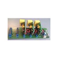
Description
KIT DEMO ENERGY METER STPMC1/S1
Manufacturer
STMicroelectronics
Type
Other Power Managementr
Specifications of STEVAL-IPE010V1
Main Purpose
Power Management, Energy/Power Meter
Embedded
No
Utilized Ic / Part
STPMC1, STPMS1
Maximum Operating Temperature
+ 85 C
Product
Power Management Development Tools
Lead Free Status / RoHS Status
Lead free / RoHS Compliant
Secondary Attributes
-
Primary Attributes
-
Lead Free Status / Rohs Status
Lead free / RoHS Compliant
For Use With/related Products
STPMC1, STPMS1
Other names
497-10754


Theory of operation
9.12
34/77
Example 10: energy registers LSB value for SYS = 0, 1, 2, 4, 5, 6, 7
This means that the reading of 0x00001 in the active energy register represents 15.258
µWh, while 0xFFFFF represents 16 Wh.
Example 11: Energy registers LSB value for SYS = 3
From 3-phase active energy wide band signal the stepper driving signals MA and MB
(output from MOP and MON pins) are generated. The frequency of these signals can be
configured as shown in paragraph
Using STPMC1 in microcontroller based meter - peripheral
operating mode (configuration bits: APL, KMOT, LVS, FUND)
The higher flexibility of the STPMC1 allows its use in microcontroller based energy meters.
In this case the STPMC1 must be programmed to work in peripheral mode setting bit APL
[1] = 0. All the SPI pins (SCS, SCLNCL, SDATD, SYN) are used only for communication
purposes, allowing the microcontroller to write and read the internal STPMC1 registers.
The peripheral mode has two further different configuration modes according to the status of
the APL configuration bit, which changes the function of MOP, MON and LED pins as
described below.
APL = 0:
In the MOP pin, the ZCR signal is available (see paragraph
The pin MON provides the WatchDOG signal. The DOG signal generates a 16 ms long
positive pulse every 1.6 seconds. Generation of these pulses can be suspended if data are
read in intervals shorter than 1.6 ms. The DOG signal is actually a watchdog reset signal
that can be used to control an operation of an on-board microcontroller. It is set to high
whenever the V
run.
It is expected that an application microcontroller should access the data in the metering
device on regular basis, at least 1/s (recommended is 32/s). Every latching of results in the
metering device requested from the microcontroller also resets the watchdog. If latching
requests does not follow each other within 1.6 second, an active high pulse on MON is
produced, because device assumes that microcontroller does not operate properly. This
signal can be either control the RESET pin of the microcontroller or it can be tied to some
interrupt pin. The second chance is recommended for a battery backup application which
can enter some sleep mode due to power down condition and should not be reset by
metering device.
The LED pin can be configured through LVS, FUND and KMOT to output different energy
signals, as shown in the table below.
C = 64000 pulses/kWh = 17.7 Hz*kW
K
K
C = 64000 pulses/kWh = 17.7 Hz*kW
K
K
K
P
Q
P
F
Q
= 30.517 *10-6 Wh
= K
= 15.258 *10-6 Wh
= K
= K
F
R
R
= 15.258 *10-6 Wh
= 15.258 *10-6 VArh
= 30.517 *10-6 VArh
CC
voltage is below 2.5 V, but after V
Doc ID 15728 Rev 4
9.13
.
CC
goes above 2.5 V this signal starts to
9.5
for details on ZCR signal);
STPMC1
Related parts for STEVAL-IPE010V1
Image
Part Number
Description
Manufacturer
Datasheet
Request
R

Part Number:
Description:
BOARD DEMO TFT DISPLAY STR91
Manufacturer:
STMicroelectronics
Datasheet:

Part Number:
Description:
BOARD EVAL FOR MEMS SENSORS
Manufacturer:
STMicroelectronics
Datasheet:

Part Number:
Description:
KIT DEV STARTER ST10F276Z5
Manufacturer:
STMicroelectronics
Datasheet:

Part Number:
Description:
BOARD EVAL HDMI $ VIDEO SWITCH
Manufacturer:
STMicroelectronics
Datasheet:

Part Number:
Description:
BOARD DEMO ACCELEROMETER DIL24
Manufacturer:
STMicroelectronics
Datasheet:

Part Number:
Description:
BOARD STLM75/STDS75/ST72F651
Manufacturer:
STMicroelectronics
Datasheet:

Part Number:
Description:
EVAL BOARD 3AXIS MEMS ACCELLRMTR
Manufacturer:
STMicroelectronics
Datasheet:

Part Number:
Description:
BOARD EVAL 8BIT MICRO + TDE1708
Manufacturer:
STMicroelectronics
Datasheet:

Part Number:
Description:
EVAL BOARD A/D TS4657
Manufacturer:
STMicroelectronics
Datasheet:

Part Number:
Description:
BOARD ADAPTER 20DIP LIS3LV02DL
Manufacturer:
STMicroelectronics
Datasheet:
Part Number:
Description:
STMicroelectronics [RIPPLE-CARRY BINARY COUNTER/DIVIDERS]
Manufacturer:
STMicroelectronics
Datasheet:
Part Number:
Description:
STMicroelectronics [LIQUID-CRYSTAL DISPLAY DRIVERS]
Manufacturer:
STMicroelectronics
Datasheet:
Part Number:
Description:
BOARD EVAL FOR MEMS SENSORS
Manufacturer:
STMicroelectronics
Datasheet: