STEVAL-IPE010V1 STMicroelectronics, STEVAL-IPE010V1 Datasheet - Page 33
STEVAL-IPE010V1
Manufacturer Part Number
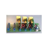
STEVAL-IPE010V1
Description
KIT DEMO ENERGY METER STPMC1/S1
Manufacturer
STMicroelectronics
Type
Other Power Managementr
Specifications of STEVAL-IPE010V1
Main Purpose
Power Management, Energy/Power Meter
Embedded
No
Utilized Ic / Part
STPMC1, STPMS1
Maximum Operating Temperature
+ 85 C
Product
Power Management Development Tools
Lead Free Status / RoHS Status
Lead free / RoHS Compliant
Secondary Attributes
-
Primary Attributes
-
Lead Free Status / Rohs Status
Lead free / RoHS Compliant
For Use With/related Products
STPMC1, STPMS1
Other names
497-10754


STPMC1
9.11
Table 16.
3-ph active energy wide band (P)
3-ph reactive energy wide band (Q)
3-ph active energy fundamental (F)
3-ph reactive energy fundamental (R)
EMI tamper condition is not available as internal status signal, but it is available (in OR with
other tamper conditions) on the SDATD pin of the device.
In peripheral application mode it is possible to detect EMI tamper comparing the value of the
16-bit DCuN and of the 12-bit RMSuN to the threshold through a microcontroller.
Energy to frequency conversion (configuration bits: APL,
KMOT, LVS, FUND)
The STPMC1 provides energy to frequency conversion both for calibration and energy
readout purposes.
The three hard-wired xDSP, implemented as four 2-channel
calculations and produce output data and signals. Inside them, each three stage decimation
filter inputs a filtered
RMS computer. All three streams of power (active, reactive and active from the fundamental
harmonic) are connected to the corresponding integrators.
Within the integrators, all three powers are accumulated into energies of 20-bit values
according to configuration bit ABS and the results are converted into pulse train signals, the
frequency of which is proportional to the accumulated energies. Each of these signals can
be brought out to the LED pin.
Due to the innovative and proprietary power calculation algorithm the frequency signal is not
affected by any ripple at twice the line frequency. This feature strongly reduces the
calibration time of the meter.
Through calibration the meter is configured to provide a certain number of pulses per kWh
(referred to as power meter constant C ) on the LED pin. According to the APL, KMOT, LVS
and FUND configuration bits, the frequency of LED signal can provide different information,
as shown in paragraphs
Given C , the number of pulses per kWh provided, the relationship between the LSB value of
the source energy registers and the number of pulses provided to LED pin is indicated in the
table below:
Energy registers LSB value
Register
signal and its integral as parallel bus or stream to the power and
9.12
and
Doc ID 15728 Rev 4
9.13
.
SYS = 0, 1, 2, 4, 5, 6, 7
K
K
K
K
R
Q
P
F
=
=
=
=
---------------- - Varh
C 2
---------------- - Varh
C 2
1000
---------------- - Wh
C 2
1000
---------------- - Wh
C 2
1000
1000
10
10
10
10
signal processors perform all
K
K
Theory of operation
K
K
R
Q
P
F
=
=
=
=
SYS = 3
-------------- - Varh
C 2
-------------- - Varh
C 2
1000
1000
-------------- - Wh
C 2
---------------- - Wh
C 2
1000
1000
9
9
9
10
33/77
Related parts for STEVAL-IPE010V1
Image
Part Number
Description
Manufacturer
Datasheet
Request
R

Part Number:
Description:
BOARD DEMO TFT DISPLAY STR91
Manufacturer:
STMicroelectronics
Datasheet:

Part Number:
Description:
BOARD EVAL FOR MEMS SENSORS
Manufacturer:
STMicroelectronics
Datasheet:

Part Number:
Description:
KIT DEV STARTER ST10F276Z5
Manufacturer:
STMicroelectronics
Datasheet:

Part Number:
Description:
BOARD EVAL HDMI $ VIDEO SWITCH
Manufacturer:
STMicroelectronics
Datasheet:

Part Number:
Description:
BOARD DEMO ACCELEROMETER DIL24
Manufacturer:
STMicroelectronics
Datasheet:

Part Number:
Description:
BOARD STLM75/STDS75/ST72F651
Manufacturer:
STMicroelectronics
Datasheet:

Part Number:
Description:
EVAL BOARD 3AXIS MEMS ACCELLRMTR
Manufacturer:
STMicroelectronics
Datasheet:

Part Number:
Description:
BOARD EVAL 8BIT MICRO + TDE1708
Manufacturer:
STMicroelectronics
Datasheet:

Part Number:
Description:
EVAL BOARD A/D TS4657
Manufacturer:
STMicroelectronics
Datasheet:

Part Number:
Description:
BOARD ADAPTER 20DIP LIS3LV02DL
Manufacturer:
STMicroelectronics
Datasheet:
Part Number:
Description:
STMicroelectronics [RIPPLE-CARRY BINARY COUNTER/DIVIDERS]
Manufacturer:
STMicroelectronics
Datasheet:
Part Number:
Description:
STMicroelectronics [LIQUID-CRYSTAL DISPLAY DRIVERS]
Manufacturer:
STMicroelectronics
Datasheet:
Part Number:
Description:
BOARD EVAL FOR MEMS SENSORS
Manufacturer:
STMicroelectronics
Datasheet: