STEVAL-IPE010V1 STMicroelectronics, STEVAL-IPE010V1 Datasheet - Page 64
STEVAL-IPE010V1
Manufacturer Part Number
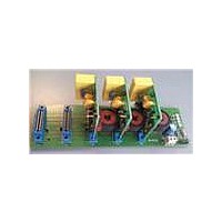
STEVAL-IPE010V1
Description
KIT DEMO ENERGY METER STPMC1/S1
Manufacturer
STMicroelectronics
Type
Other Power Managementr
Specifications of STEVAL-IPE010V1
Main Purpose
Power Management, Energy/Power Meter
Embedded
No
Utilized Ic / Part
STPMC1, STPMS1
Maximum Operating Temperature
+ 85 C
Product
Power Management Development Tools
Lead Free Status / RoHS Status
Lead free / RoHS Compliant
Secondary Attributes
-
Primary Attributes
-
Lead Free Status / Rohs Status
Lead free / RoHS Compliant
For Use With/related Products
STPMC1, STPMS1
Other names
497-10754


Theory of operation
Table 33.
Figure 24. Timing for writing configuration and mode bits
64/77
DAAAAAAA
D0000000
D1101111
76543210
Bit pos.
SCS
SCS
SYN
SYN
SCLNLC
SCLNLC
SDATD
SDATD
Functional description of commands
Example 18: Setting a configuration bit
The same procedure should be applied for the mode signals, but in this case the 7-bits
address must be taken from the relative
The lsb of command is also called EXE bit because instead of a data bit value, the
corresponding serial clock pulse is used to generate the necessary latching signal. This way
the writing mechanism does not need the measurement clock in order to operate, which
makes the operation of SPI module of STPMC1 completely independent from the rest of
device logic except from the signal POR.
Commands for changing system signals should be sent during active signals SCS and SYN
as it is shown in
driver of STPMC1 and make the SDATD as an input pin. A string of commands can be send
within one period of active signals SCS and SYN or command can be followed by reading
the data record but, in this case, the SYN should be deactivated in order to enable SDATD
output driver and a SYN pulse should be applied before activation of SCS in order to latch
the data.
t
t
1
2
−>
−>
To set the configuration bit 47 (part of the R-phase current channel calibrator) to 0, we
must convert the decimal 47 to its 7-bit binary value: 0101111. The byte command is
then composed like this:
1 bit DATA value+7-bits address = 10101111 (0xAF)
CFG000=D, (shadow of first configurator, TSTD)
CFGa=D,
CFG111=D, (shadow of last configurator, CHK)
t
t
2
3
(> 30 ns): SPI out of idle state
(> 30 ns): SPI enabled for write operation
t
t
1
1
Figure 24
(shadow of any configurator, a = AAAAAA
t
t
2
2
t
t
3
3
t
t
4
4
. The SYN must be put low in order to disable SDATD output
t
t
5
5
Doc ID 15728 Rev 4
(X, D, A = {0, 1})
Table 32
Command
.
2
< 1110000
t
t
6
6
2
)
t
t
7
7
t
t
8
8
t
t
9
9
STPMC1
Related parts for STEVAL-IPE010V1
Image
Part Number
Description
Manufacturer
Datasheet
Request
R

Part Number:
Description:
BOARD DEMO TFT DISPLAY STR91
Manufacturer:
STMicroelectronics
Datasheet:

Part Number:
Description:
BOARD EVAL FOR MEMS SENSORS
Manufacturer:
STMicroelectronics
Datasheet:

Part Number:
Description:
KIT DEV STARTER ST10F276Z5
Manufacturer:
STMicroelectronics
Datasheet:

Part Number:
Description:
BOARD EVAL HDMI $ VIDEO SWITCH
Manufacturer:
STMicroelectronics
Datasheet:

Part Number:
Description:
BOARD DEMO ACCELEROMETER DIL24
Manufacturer:
STMicroelectronics
Datasheet:

Part Number:
Description:
BOARD STLM75/STDS75/ST72F651
Manufacturer:
STMicroelectronics
Datasheet:

Part Number:
Description:
EVAL BOARD 3AXIS MEMS ACCELLRMTR
Manufacturer:
STMicroelectronics
Datasheet:

Part Number:
Description:
BOARD EVAL 8BIT MICRO + TDE1708
Manufacturer:
STMicroelectronics
Datasheet:

Part Number:
Description:
EVAL BOARD A/D TS4657
Manufacturer:
STMicroelectronics
Datasheet:

Part Number:
Description:
BOARD ADAPTER 20DIP LIS3LV02DL
Manufacturer:
STMicroelectronics
Datasheet:
Part Number:
Description:
STMicroelectronics [RIPPLE-CARRY BINARY COUNTER/DIVIDERS]
Manufacturer:
STMicroelectronics
Datasheet:
Part Number:
Description:
STMicroelectronics [LIQUID-CRYSTAL DISPLAY DRIVERS]
Manufacturer:
STMicroelectronics
Datasheet:
Part Number:
Description:
BOARD EVAL FOR MEMS SENSORS
Manufacturer:
STMicroelectronics
Datasheet: