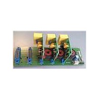
STEVAL-IPE010V1 STMicroelectronics, STEVAL-IPE010V1 Datasheet - Page 61

STEVAL-IPE010V1
Manufacturer Part Number
STEVAL-IPE010V1
Description
KIT DEMO ENERGY METER STPMC1/S1
Manufacturer
STMicroelectronics
Type
Other Power Managementr
Specifications of STEVAL-IPE010V1
Main Purpose
Power Management, Energy/Power Meter
Embedded
No
Utilized Ic / Part
STPMC1, STPMS1
Maximum Operating Temperature
+ 85 C
Product
Power Management Development Tools
Lead Free Status / RoHS Status
Lead free / RoHS Compliant
Secondary Attributes
-
Primary Attributes
-
Lead Free Status / Rohs Status
Lead free / RoHS Compliant
For Use With/related Products
STPMC1, STPMS1
Other names
497-10754
STPMC1
9.21.1
Figure 21. Timing for providing remote reset request
Note:
the SCS status. If SCS is low, SCLNCL is the input of serial bit synchronization clock signal.
When SCS is high, SCLNLC determines idle state of the SPI.
SDATD : is the data pin. If SCS is low, the operation of SDATD is dependent on the status of
SYN pin. If SYN is high SDATD is the output of serial bit data (read mode) if SYN is low
SDATD is the input of serial bit data signal (write mode). If SCS is high SDATD is input of
idle signal.
Any of the pins above has an internal weak pull-up device of a nominal 15 A. This means
that when a pin is not forced by external signals, the state of the pin is logic high. A high
state of any of the input pins above is considered in an idle (not active) state.
For the SPI to operate correctly the STPMC1 must be correctly supplied as described in the
power supply section. Idle state of SPI module is recognized when the signals of pins SYN,
SCS, SCLNLC and SDATD are in a logic high state. Any SPI operations should start from
such an idle state. The exception to this rule is when the STPMC1 has been put into
standalone application mode. In this mode it is possible that the states of the pins SCLNLC,
SDATD and SYN are not high due to the states of the corresponding internal status bits.
When SCS is active (low), signal SDATD should change its state at the trailing edge of the
signal SCLNLC and signal SDATD should be stable at the next leading edge of signal
SCLNLC. The first valid bit of SDATD is always started with activation of signal SCLNLC.
Remote reset
The timing diagram of the operation is shown in remote reset request timing. The time step
can be as short as 30 ns.
The internal reset signal is called RRR. Unlike the POR, the RRR signal does not cause the
125 ms delayed restart of the digital module. This signal does not clear the mode signals.
All the time intervals must be longer than 30 ns.
t
7
-> t
8
is the reset time, this interval must be longer than 30 ns as well.
SYN
SYN
SCLNLC
SCLNLC
SDATD
SDATD
SCS
SCS
t
t
1
1
Doc ID 15728 Rev 4
t
t
2
2
t
t
3
3
t
t
4
4
t
t
5
5
t
t
6
6
t
t
7
7
t
t
8
8
t
t
9
9
t
t
10
10
Theory of operation
61/77


