PIC18F26K22-I/ML Microchip Technology, PIC18F26K22-I/ML Datasheet - Page 482
PIC18F26K22-I/ML
Manufacturer Part Number
PIC18F26K22-I/ML
Description
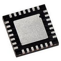
IC PIC MCU 64KB FLASH 28QFN
Manufacturer
Microchip Technology
Series
PIC® XLP™ 18Fr
Datasheets
1.PIC16F722-ISS.pdf
(8 pages)
2.PIC18F26J13-ISS.pdf
(496 pages)
3.PIC18F24K22-ISP.pdf
(494 pages)
Specifications of PIC18F26K22-I/ML
Core Size
8-Bit
Program Memory Size
64KB (32K x 16)
Core Processor
PIC
Speed
64MHz
Connectivity
I²C, SPI, UART/USART
Peripherals
Brown-out Detect/Reset, HLVD, POR, PWM, WDT
Number Of I /o
24
Program Memory Type
FLASH
Eeprom Size
1K x 8
Ram Size
3.8K x 8
Voltage - Supply (vcc/vdd)
1.8 V ~ 5.5 V
Data Converters
A/D 19x10b
Oscillator Type
Internal
Operating Temperature
-40°C ~ 85°C
Package / Case
28-VQFN Exposed Pad
Controller Family/series
PIC18
No. Of I/o's
25
Eeprom Memory Size
1KB
Ram Memory Size
3896Byte
Cpu Speed
64MHz
No. Of Timers
7
Lead Free Status / RoHS Status
Lead free / RoHS Compliant
Available stocks
Company
Part Number
Manufacturer
Quantity
Price
Company:

Part Number:
PIC18F26K22-I/ML
Manufacturer:
MICROCHIP
Quantity:
3 400
Part Number:
PIC18F26K22-I/ML
Manufacturer:
MICROCHIP/微芯
Quantity:
20 000


PIC18(L)F2X/4XK22
C
C Compilers
CALL ................................................................................ 384
CALLW ............................................................................. 413
Capture Module. See Enhanced Capture/Compare/
Capture/Compare/PWM ................................................... 179
Capture/Compare/PWM (CCP)
CCPTMRS0 Register ....................................................... 206
CCPTMRS1 Register ....................................................... 206
CCPxCON (ECCPx) Register .......................................... 203
Clock Accuracy with Asynchronous Operation ................ 274
Clock Sources
Clock Switching .................................................................. 41
CLRF ................................................................................ 385
CLRWDT .......................................................................... 385
CM1CON0 Register ......................................................... 312
CM2CON0 Register ......................................................... 313
CM2CON1 Register ......................................................... 316
Code Examples
DS41412A-page 482
MPLAB C18 ............................................................. 420
PWM(ECCP)
Associated Registers w/
Associated Registers w/ Compare ........................... 184
Associated Registers w/ PWM ......................... 189, 202
Capture Mode .......................................................... 180
CCPx Pin Configuration ........................................... 180
Compare Mode ........................................................ 183
Prescaler .................................................................. 181
PWM Mode
PWM Operation ....................................................... 186
PWM Overview ........................................................ 186
PWM Period ............................................................. 187
PWM Setup .............................................................. 186
External Modes .......................................................... 34
Internal Modes ........................................................... 36
Selecting the 31 kHz Source ...................................... 29
Selection Using OSCCON Register ........................... 29
16 x 16 Signed Multiply Routine .............................. 112
16 x 16 Unsigned Multiply Routine .......................... 112
Capture ............................ 181, 182, 185, 189, 203
CCPx Pin Configuration ................................... 183
Software Interrupt Mode .......................... 180, 183
Special Event Trigger ....................................... 184
Timer1 Mode Resource ........................... 180, 183
Duty Cycle ........................................................ 187
Effects of Reset ................................................ 188
Example PWM Frequencies and
Example PWM Frequencies and
Example PWM Frequencies and
Operation in Sleep Mode ................................. 188
Resolution ........................................................ 188
System Clock Frequency Changes .................. 188
EC ...................................................................... 34
HS ...................................................................... 35
LP ....................................................................... 35
OST .................................................................... 34
RC ...................................................................... 36
XT ...................................................................... 35
Frequency Selection .......................................... 38
INTOSC ............................................................. 36
INTOSCIO .......................................................... 36
LFINTOSC ......................................................... 38
Resolutions, 20 MHZ ............................... 188
Resolutions, 32 MHZ ............................... 188
Resolutions, 8 MHz .................................. 188
Preliminary
Code Protection ............................................................... 351
COMF .............................................................................. 386
Comparator
Comparator Module
Comparator Specifications ............................................... 441
Comparator Voltage Reference (CV
Comparator Voltage Reference (CV
Comparators
Compare Module. See Enhanced Capture/
Computed GOTO ............................................................... 73
CONFIG1H Register ........................................................ 353
CONFIG2H Register ........................................................ 355
CONFIG2L Register ........................................................ 354
CONFIG3H Register ........................................................ 356
CONFIG4L Register ........................................................ 357
CONFIG5H Register ........................................................ 358
CONFIG5L Register ........................................................ 357
CONFIG6H Register ........................................................ 359
CONFIG6L Register ........................................................ 358
CONFIG7H Register ........................................................ 360
CONFIG7L Register ........................................................ 359
Configuration Bits ............................................................ 351
Configuration Register Protection .................................... 367
Context Saving During Interrupts ..................................... 131
CPFSEQ .......................................................................... 386
CPFSGT .......................................................................... 387
CPFSLT ........................................................................... 387
CTMU
8 x 8 Signed Multiply Routine .................................. 111
8 x 8 Unsigned Multiply Routine .............................. 111
A/D Conversion ........................................................ 299
Capacitance Calibration Routine ............................. 326
Capacitive Touch Switch Routine ............................ 328
Changing Between Capture Prescalers ................... 181
Clearing RAM Using Indirect Addressing .................. 90
Computed GOTO Using an Offset Value ................... 73
Current Calibration Routine ..................................... 324
Data EEPROM Read ............................................... 107
Data EEPROM Refresh Routine .............................. 108
Data EEPROM Write ............................................... 107
Erasing a Flash Program Memory Row ................... 100
Fast Register Stack ................................................... 73
Initializing PORTA .................................................... 133
Initializing PORTB .................................................... 138
Initializing PORTC ................................................... 142
Initializing PORTD ................................................... 146
Initializing PORTE .................................................... 149
Reading a Flash Program Memory Word .................. 99
Saving Status, WREG and BSR Registers in RAM . 131
Setup for CTMU Calibration Routines ..................... 323
Writing to Flash Program Memory ................... 102–103
Associated Registers ............................................... 317
Operation ................................................................. 307
Operation During Sleep ........................................... 311
Response Time ........................................................ 309
C1 Output State Versus Input Conditions ................ 309
Effects of a Reset .................................................... 311
Response Time ........................................................ 309
C2OUT as T1 Gate .................................................. 166
Effects of a Reset .................................................... 311
Compare/PWM (ECCP)
Associated Registers ............................................... 333
Calibrating ............................................................... 322
Creating a Delay with ............................................... 330
Effects of a Reset .................................................... 331
2010 Microchip Technology Inc.
REF
REF
)
)
Related parts for PIC18F26K22-I/ML
Image
Part Number
Description
Manufacturer
Datasheet
Request
R

Part Number:
Description:
Manufacturer:
Microchip Technology Inc.
Datasheet:
Part Number:
Description:
Manufacturer:
Microchip Technology Inc.
Datasheet:
Part Number:
Description:
Manufacturer:
Microchip Technology Inc.
Datasheet:
Part Number:
Description:
Manufacturer:
Microchip Technology Inc.
Datasheet:
Part Number:
Description:
Manufacturer:
Microchip Technology Inc.
Datasheet:
Part Number:
Description:
Manufacturer:
Microchip Technology Inc.
Datasheet:
Part Number:
Description:
Manufacturer:
Microchip Technology Inc.
Datasheet:
Part Number:
Description:
Manufacturer:
Microchip Technology Inc.
Datasheet: