ATTINY261-20MUR Atmel, ATTINY261-20MUR Datasheet - Page 187
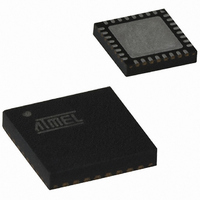
ATTINY261-20MUR
Manufacturer Part Number
ATTINY261-20MUR
Description
IC MCU AVR 2K FLASH 20MHZ 32QFN
Manufacturer
Atmel
Series
AVR® ATtinyr
Specifications of ATTINY261-20MUR
Core Processor
AVR
Core Size
8-Bit
Speed
20MHz
Connectivity
USI
Peripherals
Brown-out Detect/Reset, POR, PWM, WDT
Number Of I /o
16
Program Memory Size
2KB (1K x 16)
Program Memory Type
FLASH
Eeprom Size
128 x 8
Ram Size
128 x 8
Voltage - Supply (vcc/vdd)
2.7 V ~ 5.5 V
Data Converters
A/D 11x10b
Oscillator Type
Internal
Operating Temperature
-40°C ~ 85°C
Package / Case
32-VFQFN Exposed Pad
Lead Free Status / RoHS Status
Lead free / RoHS Compliant


19. Electrical Characteristics
19.1
19.2
Table 19-1.
2588E–AVR–08/10
Operating Temperature.................................. -55°C to +125°C
Storage Temperature ..................................... -65°C to +150°C
Voltage on any Pin except RESET
with respect to Ground ................................-0.5V to V
Voltage on RESET with respect to Ground......-0.5V to +13.0V
Maximum Operating Voltage ............................................ 6.0V
DC Current per I/O Pin ............................................... 40.0 mA
DC Current V
Symbol
V
V
V
V
I
I
R
R
IL
IH
IL
IH
OL
OH
RST
PU
Absolute Maximum Ratings*
DC Characteristics
Parameter
Input Low-voltage
Input High-voltage
Output Low Voltage
(Except Reset pin)
Output High-voltage
(Except Reset pin)
Input Leakage
Current I/O Pin
Input Leakage
Current I/O Pin
Reset Pull-up Resistor
I/O Pin Pull-up Resistor
CC
DC Characteristics. T
and GND Pins ................................ 200.0 mA
(6)
(6)
(4)
(5)
A
= -40°C to +85°C, V
XTAL1 pin,
External Clock Selected
RESET pin
RESET pin as I/O
I
Condition
Except XTAL1 and
RESET pins
Except XTAL1 and
RESET pins
XTAL1 pin,
External Clock Selected
RESET pin
RESET pin as I/O
I
I
I
Vcc = 5.5V, pin low
(absolute value)
Vcc = 5.5V, pin high
(absolute value)
OL
OL
OH
OH
= 10 mA, V
= 5 mA, V
= -10 mA, V
= -5 mA, V
CC
CC
CC
CC
+0.5V
CC
= 3V
= 3V
= 5V
= 5V
CC
= 1.8V to 5.5V (unless otherwise noted).
*NOTICE:
0.7V
0.8V
0.9V
0.7V
Min
-0.5
-0.5
-0.5
-0.5
4.3
2.5
30
20
CC
CC
CC
CC
(2)
(2)
(2)
(2)
Stresses beyond those listed under “Absolute
Maximum Ratings” may cause permanent dam-
age to the device. This is a stress rating only and
functional operation of the device at these or
other conditions beyond those indicated in the
operational sections of this specification is not
implied. Exposure to absolute maximum rating
conditions for extended periods may affect
device reliability.
Typ
< 0.05
< 0.05
(1)
0.2V
0.1V
0.2V
0.2V
V
V
V
V
CC
CC
CC
CC
Max
0.6
0.5
60
50
1
1
+0.5
+0.5
+0.5
+0.5
CC
CC
CC
CC
(3)
(3)
(3)
(3)
Units
kΩ
kΩ
µA
µA
V
V
V
V
V
V
V
V
V
V
V
V
187
Related parts for ATTINY261-20MUR
Image
Part Number
Description
Manufacturer
Datasheet
Request
R

Part Number:
Description:
Manufacturer:
Atmel Corporation
Datasheet:
Part Number:
Description:
Manufacturer:
Atmel Corporation
Datasheet:

Part Number:
Description:
IC MCU AVR 2K FLASH 20MHZ 32-QFN
Manufacturer:
Atmel
Datasheet:

Part Number:
Description:
IC MCU AVR 2K FLASH 20MHZ 20-DIP
Manufacturer:
Atmel
Datasheet:

Part Number:
Description:
MCU AVR 2K FLASH 15MHZ 32-QFN
Manufacturer:
Atmel
Datasheet:
Part Number:
Description:
MCU AVR 2KB FLASH 15MHZ 32-VQFN
Manufacturer:
Atmel
Datasheet:

Part Number:
Description:
IC MCU AVR 2K FLASH 20MHZ 20SOIC
Manufacturer:
Atmel
Datasheet:
Part Number:
Description:
Attiny261 8-bit Microcontroller With 2/4/8k Bytes In-system Programmable Flash
Manufacturer:
ATMEL Corporation
Datasheet:

Part Number:
Description:
IC MCU AVR 2K FLASH 20MHZ 20SOIC
Manufacturer:
Atmel
Datasheet:
Part Number:
Description:
Manufacturer:
Atmel Corporation
Datasheet: