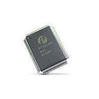
PI7C21P100BNHE Pericom Semiconductor, PI7C21P100BNHE Datasheet - Page 37

PI7C21P100BNHE
Manufacturer Part Number
PI7C21P100BNHE
Description
Peripheral Drivers & Components (PCIs) PCI-X to PCI-XBridge 2 Port
Manufacturer
Pericom Semiconductor
Datasheet
1.PI7C21P100BNHE.pdf
(79 pages)
Specifications of PI7C21P100BNHE
Maximum Operating Temperature
+ 70 C
Minimum Operating Temperature
0 C
Mounting Style
SMD/SMT
Operating Supply Voltage
3 V to 3.6 V
Package / Case
CSBGA-304
Lead Free Status / RoHS Status
Lead free / RoHS Compliant
Available stocks
Company
Part Number
Manufacturer
Quantity
Price
Company:
Part Number:
PI7C21P100BNHE
Manufacturer:
Pericom
Quantity:
135
Company:
Part Number:
PI7C21P100BNHE
Manufacturer:
PI
Quantity:
1 831
6.3.3
6.3.4
Table 6-1 PROGRAMMABLE PULL-UP CIRCUIT
CLOCK STABILITY
To comply with PCI and PCI-X architecture specifications, the bus clock must be stable and
running at the designated frequency for at least 100us after deassertion of the bus reset.
S_CLK_STABLE is used to determine and detect when S_CLK has become stable. During a
bus reset, PI7C21P100B will wait for the assertion of S_CLK_STABLE before determining
the mode and frequency. PI7C21P100B is expecting no more than one transition on the
S_CLK_STABLE input from the “not stable” to the “stable” state. S_CLK_STABLE input
may be tied HIGH if the secondary clock input is known to be always stable prior to the
deassertion of the primary bus reset signal or the secondary bus reset bit of the bridge control
register. Examples of sources for S_CLK_STABLE are lock indicators on circuits that
employ PLL’s or “power good” indicators.
DRIVER IMPEDANCE SELECTION
The output drivers on PI7C21P100B are capable of two different output impedances, 40 ohm
output impedance and a 20 ohm. The output impedance for the primary and secondary
interfaces is separately controlled. PI7C21P100B selects a default impedance value at the
deassertion of the bus reset based on the bus mode and frequency. If a bus is configured to be
in PCI-X 133 mode, it is assumed that the bus will have fewer devices and have a higher
impedance. In this case, the drivers utilize the 40 ohm output impedance mode. The 20 ohm
output impedance mode is utilized for all other PCI-X and all PCI configurations, assuming
that the bus is more heavily loaded and has lower impedance. Some applications do not
follow these assumptions so two control signals are provided; P_DRVR for the primary and
S_DRVR for the secondary. When these inputs are pulled HIGH, PI7C21P100B will change
the output impedance of the drivers on their respective interfaces to the opposite state than
was assumed by default, as shown in Table 6-2. The driver mode may not be changed
dynamically, but can be changed during each bus reset.
Page 37 of 79
2-PORT PCI-X TO PCI-X BRIDGE
November 2005 – Revision 1.02
PI7C21P100B


