UPD78F9222MC(T)-5A4-A NEC, UPD78F9222MC(T)-5A4-A Datasheet - Page 11
UPD78F9222MC(T)-5A4-A
Manufacturer Part Number
UPD78F9222MC(T)-5A4-A
Description
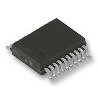
8BIT MCU, 4K FLASH, 256B RAM, 78F9222
Manufacturer
NEC
Datasheet
1.UPD78F9222MCT-5A4-A.pdf
(414 pages)
Specifications of UPD78F9222MC(T)-5A4-A
Controller Family/series
UPD78
No. Of I/o's
17
Ram Memory Size
256Byte
Cpu Speed
10MHz
No. Of Timers
4
No. Of
RoHS Compliant
Core Size
8bit
Program Memory Size
4KB
Oscillator Type
External, Internal
Available stocks
Company
Part Number
Manufacturer
Quantity
Price
Company:

Part Number:
UPD78F9222MC(T)-5A4-A
Manufacturer:
NEC
Quantity:
1 000
Company:
Part Number:
UPD78F9222MC(T)-5A4-A
Manufacturer:
NEC/PBF
Quantity:
6 640
Part Number:
UPD78F9222MC(T)-5A4-A
Manufacturer:
RENESAS/瑞萨
Quantity:
20 000


CHAPTER 13 STANDBY FUNCTION..................................................................................................230
CHAPTER 14 RESET FUNCTION .......................................................................................................240
CHAPTER 15 POWER-ON-CLEAR CIRCUIT .....................................................................................248
CHAPTER 16 LOW-VOLTAGE DETECTOR.......................................................................................252
CHAPTER 17 OPTION BYTE ...............................................................................................................262
CHAPTER 18 FLASH MEMORY..........................................................................................................265
12.3 Interrupt Function Control Registers.....................................................................................220
12.4 Interrupt Servicing Operation.................................................................................................225
13.1 Standby Function and Configuration ....................................................................................230
13.2 Standby Function Operation ..................................................................................................233
14.1 Register for Confirming Reset Source ..................................................................................247
15.1 Functions of Power-on-Clear Circuit .....................................................................................248
15.2 Configuration of Power-on-Clear Circuit...............................................................................249
15.3 Operation of Power-on-Clear Circuit .....................................................................................249
15.4 Cautions for Power-on-Clear Circuit......................................................................................250
16.1 Functions of Low-Voltage Detector .......................................................................................252
16.2 Configuration of Low-Voltage Detector.................................................................................252
16.3 Registers Controlling Low-Voltage Detector ........................................................................253
16.4 Operation of Low-Voltage Detector .......................................................................................255
16.5 Cautions for Low-Voltage Detector........................................................................................259
17.1 Functions of Option Byte ........................................................................................................262
17.2 Format of Option Byte .............................................................................................................263
17.3 Caution When the RESET Pin Is Used as an Input-Only Port Pin (P34).............................264
18.1 Features ....................................................................................................................................265
18.2 Memory Configuration.............................................................................................................266
18.3 Functional Outline ...................................................................................................................267
18.4 Writing with Flash Memory Programmer...............................................................................268
18.5 Programming Environment.....................................................................................................269
18.6 Pin Connection on Board........................................................................................................271
18.7 On-Board and Off-Board Flash Memory Programming .......................................................274
12.4.1
12.4.2
12.4.3
13.1.1
13.1.2
13.2.1
13.2.2
18.6.1
18.6.2
18.6.3
18.6.4
Maskable interrupt request acknowledgment operation ............................................................ 225
Multiple interrupt servicing......................................................................................................... 227
Interrupt request pending .......................................................................................................... 229
Standby function........................................................................................................................ 230
Registers used during standby .................................................................................................. 232
HALT mode ............................................................................................................................... 233
STOP mode .............................................................................................................................. 236
X1 and X2 pins .......................................................................................................................... 271
RESET pin ................................................................................................................................ 272
Port pins .................................................................................................................................... 273
Power supply............................................................................................................................. 273
User’s Manual U16898EJ5V0UD
11
Related parts for UPD78F9222MC(T)-5A4-A
Image
Part Number
Description
Manufacturer
Datasheet
Request
R

Part Number:
Description:
16/8 bit single-chip microcomputer
Manufacturer:
NEC
Datasheet:
Part Number:
Description:
Dual audio power amp circuit
Manufacturer:
NEC
Datasheet:
Part Number:
Description:
Dual comparator
Manufacturer:
NEC
Datasheet:
Part Number:
Description:
MOS type composite field effect transistor
Manufacturer:
NEC
Datasheet:
Part Number:
Description:
50 V/100 mA FET array incorporating 2 N-ch MOSFETs
Manufacturer:
NEC
Datasheet:
Part Number:
Description:
6-pin small MM high-frequency double transistor
Manufacturer:
NEC
Datasheet:
Part Number:
Description:
6-pin small MM high-frequency double transistor
Manufacturer:
NEC
Datasheet:
Part Number:
Description:
6-pin small MM high-frequency double transistor
Manufacturer:
NEC
Datasheet:
Part Number:
Description:
6-pin small MM high-frequency double transistor
Manufacturer:
NEC
Datasheet:
Part Number:
Description:
Twin transistors equipped with different model chips(6P small MM)
Manufacturer:
NEC
Datasheet:
Part Number:
Description:
Bipolar analog integrated circuit
Manufacturer:
NEC
Datasheet: