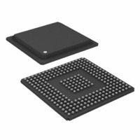
ADSP-BF535PBBZ-200 Analog Devices Inc, ADSP-BF535PBBZ-200 Datasheet - Page 7

ADSP-BF535PBBZ-200
Manufacturer Part Number
ADSP-BF535PBBZ-200
Description
200/400MMAC 16-bit DSP MICROCOMPUTER
Manufacturer
Analog Devices Inc
Series
Blackfin®r
Type
Fixed Pointr
Specifications of ADSP-BF535PBBZ-200
Interface
PCI, SPI, SSP, UART, USB
Clock Rate
200MHz
Non-volatile Memory
External
On-chip Ram
308kB
Voltage - I/o
3.30V
Voltage - Core
1.50V
Operating Temperature
-40°C ~ 85°C
Mounting Type
Surface Mount
Package / Case
260-BGA
Lead Free Status / RoHS Status
Lead free / RoHS Compliant
Available stocks
Company
Part Number
Manufacturer
Quantity
Price
Company:
Part Number:
ADSP-BF535PBBZ-200
Manufacturer:
Analog Devices Inc
Quantity:
10 000
Table 2. System Interrupt Controller (SIC) (continued)
Event Control
The ADSP-BF535 Blackfin processor provides the user with a
very flexible mechanism to control the processing of events. In
the CEC, three registers are used to coordinate and control
events. Each of the registers is 16 bits wide, and each bit repre-
sents a particular event class:
The SIC allows further control of event processing by providing
three 32-bit interrupt control and status registers. Each register
contains a bit corresponding to each of the peripheral interrupt
events shown in
REV. A
Peripheral Interrupt
Event
Memory DMA
Software Watchdog Timer
Reserved
Software Interrupt 1
Software Interrupt 2
CEC Interrupt Latch Register (ILAT)—The ILAT
register indicates when events have been latched. The
appropriate bit is set when the processor has latched the
event and cleared when the event has been accepted into
the system. This register is updated automatically by the
controller but may be read while in supervisor mode.
CEC Interrupt Mask Register (IMASK)—The IMASK
register controls the masking and unmasking of individual
events. When a bit is set in the IMASK register, that event
is unmasked and will be processed by the CEC when
asserted. A cleared bit in the IMASK register masks the
event thereby preventing the processor from servicing the
event even though the event may be latched in the ILAT
register. This register may be read from or written to while
in supervisor mode. (Note that general-purpose inter-
rupts can be globally enabled and disabled with the STI
and CLI instructions, respectively.)
CEC Interrupt Pending Register (IPEND)—The
IPEND register keeps track of all nested events. A set bit
in the IPEND register indicates the event is currently
active or nested at some level. This register is updated
automatically by the controller but may be read while in
supervisor mode.
SIC Interrupt Mask Register (SIC_IMASK)—This
register controls the masking and unmasking of each
peripheral interrupt event. When a bit is set in the register,
that peripheral event is unmasked and will be processed
by the system when asserted. A cleared bit in the register
masks the peripheral event thereby preventing the
processor from servicing the event.
SIC Interrupt Status Register (SIC_ISTAT)—As
multiple peripherals can be mapped to a single event, this
register allows the software to determine which peripheral
Table
2.
Peripheral
Interrupt ID
19
20
26–21
27
28
Default
Mapping
IVG13
IVG13
IVG14
IVG15
–7–
Because multiple interrupt sources can map to a single general-
purpose interrupt, multiple pulse assertions can occur
simultaneously, before or during interrupt processing for an
interrupt event already detected on this interrupt input. The
IPEND register contents are monitored by the SIC as the
interrupt acknowledgement.
The appropriate ILAT register bit is set when an interrupt rising
edge is detected (detection requires two core clock cycles). The
bit is cleared when the respective IPEND register bit is set. The
IPEND bit indicates that the event has entered into the processor
pipeline. At this point, the CEC will recognize and queue the next
rising edge event on the corresponding event input. The
minimum latency from the rising edge transition of the general-
purpose interrupt to the IPEND output asserted is three core
clock cycles; however, the latency can be much higher, depending
on the activity within and the mode of the processor.
DMA Controllers
The ADSP-BF535 Blackfin processor has multiple, independent
DMA controllers that support automated data transfers with
minimal overhead for the Blackfin processor core. DMA transfers
can occur between the ADSP-BF535 Blackfin processor's
internal memories and any of its DMA-capable peripherals.
Additionally, DMA transfers can be accomplished between any
of the DMA-capable peripherals and external devices connected
to the external memory interfaces, including the SDRAM con-
troller, the asynchronous memory controller and the PCI bus
interface. DMA-capable peripherals include the SPORTs, SPI
ports, UARTs, and USB port. Each individual DMA-capable
peripheral has at least one dedicated DMA channel. DMA to and
from PCI is accomplished by the memory DMA channel.
To describe each DMA sequence, the DMA controller uses a set
of parameters called a descriptor block. When successive DMA
sequences are needed, these descriptor blocks can be linked or
chained together, so the completion of one DMA sequence auto-
initiates and starts the next sequence. The descriptor blocks
include full 32-bit addresses for the base pointers for source and
destination, enabling access to the entire ADSP-BF535 Blackfin
processor address space.
In addition to the dedicated peripheral DMA channels, there is
a separate memory DMA channel provided for transfers between
the various memories of the ADSP-BF535 Blackfin processor
system. This enables transfers of blocks of data between any of
the memories, including on-chip Level 2 memory, external
SDRAM, ROM, SRAM, and flash memory, and PCI address
spaces with little processor intervention.
event source triggered the interrupt. A set bit indicates
the peripheral is asserting the interrupt, a cleared bit
indicates the peripheral is not asserting the event.
SIC Interrupt Wakeup Enable Register (SIC_IWR)—By
enabling the corresponding bit in this register, each
peripheral can be configured to wake up the processor,
should the processor be in a powered down mode when
the event is generated.
on Page
11.)
(See Dynamic Power Management
ADSP-BF535


