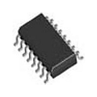
SI3018-F-FSR Silicon Laboratories Inc, SI3018-F-FSR Datasheet - Page 49

SI3018-F-FSR
Manufacturer Part Number
SI3018-F-FSR
Description
Modem Chip Chipset 16-Pin SOIC T/R
Manufacturer
Silicon Laboratories Inc
Datasheet
1.SI3018-F-FSR.pdf
(112 pages)
Specifications of SI3018-F-FSR
Package
16SOIC
Main Category
Chipset
Sub-category
Data/Voice
Typical Operating Supply Voltage
3.3 V
Power Supply Type
Digital
Typical Supply Current
8.5 mA
Minimum Operating Supply Voltage
3 V
Maximum Operating Supply Voltage
3.6 V
Data Rate
54.6875Kbps
Operating Supply Voltage (typ)
3.3V
Operating Supply Voltage (min)
3V
Operating Supply Voltage (max)
3.6V
Operating Temp Range
0C to 70C
Operating Temperature Classification
Commercial
Pin Count
16
Mounting
Surface Mount
Lead Free Status / Rohs Status
Compliant
Available stocks
Company
Part Number
Manufacturer
Quantity
Price
Company:
Part Number:
SI3018-F-FSR
Manufacturer:
SiliconL
Quantity:
52 026
Company:
Part Number:
SI3018-F-FSR
Manufacturer:
SILICON
Quantity:
57
Part Number:
SI3018-F-FSR
Manufacturer:
SILICONLABS/芯科
Quantity:
20 000
(SC) for communicating status of the device and for
initiating commands. Within the SC channel are six
Command/Indicate (C/I) bits and two handshaking bits
(MR and MX). The C/I bits are used for status and
command communication, whereas the handshaking
bits Monitor Receive (MR) and Monitor Transmit (MX)
are used for data exchanges in the Monitor channel.
Figure 41 illustrates the contents of a GCI highway
frame.
5.37. Companding in GCI Mode
The Si3050 supports µ-Law and A-Law companding
formats in addition to 8-bit or 16-bit linear data. The 8-bit
companding
Companding in PCM Mode" on page 42 and are shown
in Table 21 and Table 22. If 16-bit linear mode is used,
the resulting 16-bit samples are transmitted in both the
B1 and B2 channels of a single subframe. For proper
operation, select all Si3050 DAAs to use the B1 channel
with only one DAA per subframe.
5.38. 16 kHz Sampling Operation in GCI
The Si3050 can be configured to support a 16 kHz
sampling rate (as described in "5.34. 16 kHz Sampling
Operation in PCM Mode" on page 42) and transmit the
data on an 8 kHz GCI Highway bus. If 8-bit samples are
FSYNC
Mode
schemes
Sub-Frame
SF0
Channel
Figure 41. Time-Multiplexed GCI Highway Frame Structure
B1
8
0
are
SF1
described
SF2
B2
8
1
in
"5.33.
SF3
Rev. 1.31
125 s
used with a 16 kHz sample rate, the samples are
transmitted in both the B1 and B2 channels of a single
subframe. If 16-bit linear mode is used, the resulting
16-bit samples are transmitted in both the B1 and B2
channels of two consecutive subframes. In this case,
assign one DAA per two subframes.
5.39. Monitor Channel
The Monitor channel is used for initialization and setup
of the Si3050. It also can be used for general
communication with the Si3050 by allowing read and
write access to the Si3050’s registers. Use of the
monitor channel requires manipulation of the MR and
MX handshaking bits, located in bits 1 and 0 of the SC
channel described below. For purposes of this
specification, “downstream” is identified to be the data
sent by a host to the Si3050. “Upstream” is identified to
be the data sent by the Si3050 to a host.
Figure 41 illustrates the Monitor channel communication
protocol. For successful communication with the
Si3050, the transmitter should anticipate the falling
edge of the receiver’s acknowledgement. This also
maximizes communication speed. Because of the
handshaking
communication, the data transfer rate using the Monitor
channel is less than 8 kbytes/second.
M
8
2
SF4
Si3050 + Si3018/19
SF5
SC Channel
protocol
C/I
6
MR MX
1
SF6
required
1
SF7
for
successful
49


