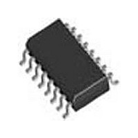
SI3018-F-FSR Silicon Laboratories Inc, SI3018-F-FSR Datasheet - Page 73

SI3018-F-FSR
Manufacturer Part Number
SI3018-F-FSR
Description
Modem Chip Chipset 16-Pin SOIC T/R
Manufacturer
Silicon Laboratories Inc
Datasheet
1.SI3018-F-FSR.pdf
(112 pages)
Specifications of SI3018-F-FSR
Package
16SOIC
Main Category
Chipset
Sub-category
Data/Voice
Typical Operating Supply Voltage
3.3 V
Power Supply Type
Digital
Typical Supply Current
8.5 mA
Minimum Operating Supply Voltage
3 V
Maximum Operating Supply Voltage
3.6 V
Data Rate
54.6875Kbps
Operating Supply Voltage (typ)
3.3V
Operating Supply Voltage (min)
3V
Operating Supply Voltage (max)
3.6V
Operating Temp Range
0C to 70C
Operating Temperature Classification
Commercial
Pin Count
16
Mounting
Surface Mount
Lead Free Status / Rohs Status
Compliant
Available stocks
Company
Part Number
Manufacturer
Quantity
Price
Company:
Part Number:
SI3018-F-FSR
Manufacturer:
SiliconL
Quantity:
52 026
Company:
Part Number:
SI3018-F-FSR
Manufacturer:
SILICON
Quantity:
57
Part Number:
SI3018-F-FSR
Manufacturer:
SILICONLABS/芯科
Quantity:
20 000
Register 18. International Control 3
Reset settings = 0000_0000
Bit
Bit
7:3
1
0
2
1
0
Name
Type
Bit
Reserved Read returns zero.
Reserved This bit may be written to a zero or one.
Reserved Read returns zero.
RFWE
Name
Name
ROV
BTD
Ring Detector Full-Wave Rectifier Enable.
When RNGV (Register 24) is disabled, this bit controls the ring detector mode and the asser-
tion of the RGDT pin. When RNGV is enabled, this bit configures the RGDT pin to either follow
the ringing signal detected by the ring validation circuit, or to follow an unqualified ring detect
one-shot signal initiated by a ring-threshold crossing and terminated by a fixed counter timeout
of approximately 5 seconds.
RNGV
D7
Receive Overload.
This bit is set when the receive input has an excessive input level (i.e., receive pin goes below
ground). Writing a 0 to this location clears this bit and the ROVI bit (Register 4, bit 6).
0 = Normal receive input level.
1 = Excessive receive input level.
Billing Tone Detected.
This bit is set if an event, such as a billing tone, causes a disruption in the line-side power
supply. Writing a zero to BTE clears this bit.
0 = No billing tone detected.
1 = Billing tone detected.
0
0
1
1
D6
RFWE
0
1
0
1
D5
RGDT
Half-Wave
Full-Wave
Validated Ring Envelope
Ring Threshold Crossing One-Shot
Rev. 1.31
D4
Function
Function
D3
Si3050 + Si3018/19
D2
RFWE
R/W
D1
D0
73


