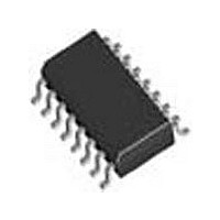
SI3018-F-FSR Silicon Laboratories Inc, SI3018-F-FSR Datasheet - Page 60

SI3018-F-FSR
Manufacturer Part Number
SI3018-F-FSR
Description
Modem Chip Chipset 16-Pin SOIC T/R
Manufacturer
Silicon Laboratories Inc
Datasheet
1.SI3018-F-FSR.pdf
(112 pages)
Specifications of SI3018-F-FSR
Package
16SOIC
Main Category
Chipset
Sub-category
Data/Voice
Typical Operating Supply Voltage
3.3 V
Power Supply Type
Digital
Typical Supply Current
8.5 mA
Minimum Operating Supply Voltage
3 V
Maximum Operating Supply Voltage
3.6 V
Data Rate
54.6875Kbps
Operating Supply Voltage (typ)
3.3V
Operating Supply Voltage (min)
3V
Operating Supply Voltage (max)
3.6V
Operating Temp Range
0C to 70C
Operating Temperature Classification
Commercial
Pin Count
16
Mounting
Surface Mount
Lead Free Status / Rohs Status
Compliant
Available stocks
Company
Part Number
Manufacturer
Quantity
Price
Company:
Part Number:
SI3018-F-FSR
Manufacturer:
SiliconL
Quantity:
52 026
Company:
Part Number:
SI3018-F-FSR
Manufacturer:
SILICON
Quantity:
57
Part Number:
SI3018-F-FSR
Manufacturer:
SILICONLABS/芯科
Quantity:
20 000
Si3050 + Si3018/19
Register 1. Control 1
Reset settings = 0000_0000
60
Bit
5:4
7
6
3
2
1
0
Name
Type
Bit
PWMM[1:0] Pulse Width Modulation Mode.
Reserved Read returns zero.
Reserved Read returns zero.
Reserved Read returns zero.
PWME
Name
IDL
SR
R/W
SR
D7
Software Reset.
0 = Enables the DAA for normal operation.
1 = Sets all registers to their reset value.
Note: Bit automatically clears after being set.
Used to select the type of signal output on the call progress AOUT pin.
00 = PWM output is clocked at 16.384 MHz as a delta-sigma data stream. A local density of
1s and 0s tracks the combined transmit and receive signals. Use this setting with the optional
call progress circuit shown in Figure 18 on page 19.
01 = Balanced conventional PWM output signal has high and low portions of the modulated
pulse that are centered on the 16 kHz sample clock.
10 = Conventional PWM output signal returns to logic 0 at regular 32 kHz intervals and rises
at a time in the 32 kHz period proportional to its instantaneous amplitude.
11 = Reserved.
Pulse Width Modulation Enable.
0 = Pulse width modulation mode disabled (AOUT).
1 = Enable pulse width modulation mode for the call progress analog output (AOUT). This
mode sums the transmit and receive audio paths and presents this as a CMOS digital-level
output of PWM data. The circuit in Figure 18 on page 19 should be used.
Isolation Digital Loopback.
0 = Digital loopback across the isolation barrier is disabled.
1 = Enables digital loopback mode across the isolation barrier. The line-side device must be
enabled and off-hook prior to setting this mode. The data path includes the TX and RX filters.
D6
D5
PWMM[1:0]
R/W
Rev. 1.31
D4
Function
PWME
R/W
D3
D2
R/W
IDL
D1
D0


