DS21FF44 Maxim Integrated Products, DS21FF44 Datasheet - Page 18
DS21FF44
Manufacturer Part Number
DS21FF44
Description
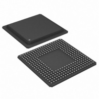
IC FRAMER E1 4X4 16CH 300-BGA
Manufacturer
Maxim Integrated Products
Datasheet
1.DS21FT44N.pdf
(117 pages)
Specifications of DS21FF44
Controller Type
E1 Framer
Interface
Parallel/Serial
Voltage - Supply
2.97 V ~ 3.63 V
Current - Supply
300mA
Operating Temperature
0°C ~ 70°C
Mounting Type
Surface Mount
Package / Case
300-BGA
Lead Free Status / RoHS Status
Contains lead / RoHS non-compliant
Available stocks
Company
Part Number
Manufacturer
Quantity
Price


6. DS21Q44 INTRODUCTION
The DS21Q44 is a superset version of the popular DS21Q43 quad E1 framer offering the new features
listed below. All of the original features of the DS21Q43 have been retained and software created for the
original device is transferable to the DS21Q44.
NEW FEATURES
§ Additional hardware signaling capability including:
§ Per–channel code insertion in both transmit and receive paths
§ Full HDLC controller with 64-byte buffers in both transmit and receive paths. Configurable for Sa
§ RCL, RLOS, RRA, and RUA1 alarms now interrupt on change of state
§ 8.192MHz clock synthesizer
§ Ability to monitor one DS0 channel in both the transmit and receive paths
§ Option to extend carrier loss criteria to a 1 ms period as per ETS 300 233
§ Automatic RAI generation to ETS 300 011 specifications
§ IEEE 1149.1 support
FUNCTIONAL DESCRIPTION
The receive side in each framer locates FAS frame and CRC and CAS multiframe boundaries as well as
detects incoming alarms including, carrier loss, loss of synchronization, AIS and Remote Alarm. If
needed, the receive side elastic store can be enabled in order to absorb the phase and frequency
differences between the recovered E1 data stream and an asynchronous backplane clock, which is
provided at the RSYSCLK input. The clock applied at the RSYSCLK input can be either a 2.048 MHz
clock or a 1.544 MHz clock. The RSYSCLK can be a burst clock with speeds up to 8.192 MHz.
The transmit side in each framer is totally independent from the receive side in both the clock
requirements and characteristics. Data off of a backplane can be passed through a transmit side elastic
store if necessary. The transmit formatter will provide the necessary frame/multiframe data overhead for
E1 transmission.
READER’S NOTE:
This data sheet assumes a particular nomenclature of the E1 operating environment. In each 125µs frame,
there are 32 8-bit timeslots numbered 0 to 31. Timeslot 0 is transmitted first and received first. These 32
timeslots are also referred to as channels with a numbering scheme of 1 to 32. Timeslot 0 is identical to
channel 1, timeslot 1 is identical to Channel 2, and so on. Each timeslot (or channel) is made up of 8 bits,
which are numbered 1 to 8. Bit number 1 is the MSB and is transmitted first. Bit number 8 is the LSB and
is transmitted last. Throughout this data sheet, the following abbreviations are used:
FAS
CAS
MF
Si
–
–
–
–
bits or DS0 access
receive signaling reinsertion to a backplane multiframe sync
availability of signaling in a separate PCM data stream
signaling freezing
interrupt generated on change of signaling data
Frame Alignment Signal
Channel Associated Signaling
Multiframe
International bits
18 of 117
Sa
E-bit
CRC4
CCS
Cyclical Redundancy Check
Common Channel Signaling
Additional bits
CRC4 Error Bits
Related parts for DS21FF44
Image
Part Number
Description
Manufacturer
Datasheet
Request
R

Part Number:
Description:
MAX7528KCWPMaxim Integrated Products [CMOS Dual 8-Bit Buffered Multiplying DACs]
Manufacturer:
Maxim Integrated Products
Datasheet:
Part Number:
Description:
Single +5V, fully integrated, 1.25Gbps laser diode driver.
Manufacturer:
Maxim Integrated Products
Datasheet:
Part Number:
Description:
Single +5V, fully integrated, 155Mbps laser diode driver.
Manufacturer:
Maxim Integrated Products
Datasheet:
Part Number:
Description:
VRD11/VRD10, K8 Rev F 2/3/4-Phase PWM Controllers with Integrated Dual MOSFET Drivers
Manufacturer:
Maxim Integrated Products
Datasheet:
Part Number:
Description:
Highly Integrated Level 2 SMBus Battery Chargers
Manufacturer:
Maxim Integrated Products
Datasheet:
Part Number:
Description:
Current Monitor and Accumulator with Integrated Sense Resistor; ; Temperature Range: -40°C to +85°C
Manufacturer:
Maxim Integrated Products
Part Number:
Description:
TSSOP 14/A�/RS-485 Transceivers with Integrated 100O/120O Termination Resis
Manufacturer:
Maxim Integrated Products
Part Number:
Description:
TSSOP 14/A�/RS-485 Transceivers with Integrated 100O/120O Termination Resis
Manufacturer:
Maxim Integrated Products
Part Number:
Description:
QFN 16/A�/AC-DC and DC-DC Peak-Current-Mode Converters with Integrated Step
Manufacturer:
Maxim Integrated Products
Part Number:
Description:
TDFN/A/65V, 1A, 600KHZ, SYNCHRONOUS STEP-DOWN REGULATOR WITH INTEGRATED SWI
Manufacturer:
Maxim Integrated Products
Part Number:
Description:
Integrated Temperature Controller f
Manufacturer:
Maxim Integrated Products
Part Number:
Description:
SOT23-6/I�/45MHz to 650MHz, Integrated IF VCOs with Differential Output
Manufacturer:
Maxim Integrated Products
Part Number:
Description:
SOT23-6/I�/45MHz to 650MHz, Integrated IF VCOs with Differential Output
Manufacturer:
Maxim Integrated Products
Part Number:
Description:
EVALUATION KIT/2.4GHZ TO 2.5GHZ 802.11G/B RF TRANSCEIVER WITH INTEGRATED PA
Manufacturer:
Maxim Integrated Products
Part Number:
Description:
QFN/E/DUAL PCIE/SATA HIGH SPEED SWITCH WITH INTEGRATED BIAS RESISTOR
Manufacturer:
Maxim Integrated Products
Datasheet: