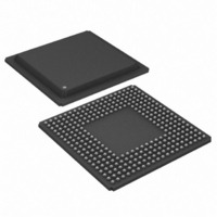
DS21FF44 Maxim Integrated Products, DS21FF44 Datasheet - Page 38

DS21FF44
Manufacturer Part Number
DS21FF44
Description
IC FRAMER E1 4X4 16CH 300-BGA
Manufacturer
Maxim Integrated Products
Datasheet
1.DS21FT44N.pdf
(117 pages)
Specifications of DS21FF44
Controller Type
E1 Framer
Interface
Parallel/Serial
Voltage - Supply
2.97 V ~ 3.63 V
Current - Supply
300mA
Operating Temperature
0°C ~ 70°C
Mounting Type
Surface Mount
Package / Case
300-BGA
Lead Free Status / RoHS Status
Contains lead / RoHS non-compliant
Available stocks
Company
Part Number
Manufacturer
Quantity
Price
CCR2: COMMON CONTROL REGISTER 2 (Address = 1A Hex)
AUTOMATIC ALARM GENERATION
The DS21Q44 can be programmed to automatically transmit AIS or Remote Alarm. When automatic AIS
generation is enabled (CCR2.5 = 1), the framer monitors the receive side to determine if any of the
following conditions are present: loss of receive frame synchronization, AIS alarm (all one’s) reception,
or loss of receive carrier (or signal). If any one (or more) of the above conditions is present, then the
framer will transmit an AIS alarm.
When automatic RAI generation is enabled (CCR2.4 = 1), the framer monitors the receive side to
determine if any of the following conditions are present: loss of receive frame synchronization, AIS alarm
(all one’s) reception, loss of receive carrier or if CRC4 multiframe synchronization (if enabled) cannot be
found within 128ms of FAS synchronization. If any one (or more) of the above conditions is present, then
the framer will transmit a RAI alarm. RAI generation conforms to ETS 300 011 specifications and a
(MSB)
ECUS
SYMBOL
LOTCMC
VCRFS
RSERC
ECUS
AAIS
ARA
RFE
RFF
VCRFS
POSITION
CCR2.7
CCR2.6
CCR2.5
CCR2.4
CCR2.3
CCR2.2
CCR2.1
CCR2.0
AAIS
Error Counter Update Select. See Section 12 for details.
0 = update error counters once a second
1 = update error counters every 62.5ms (500 frames)
VCR Function Select. See Section 12 for details.
0 = count BiPolar Violations (BPVs)
1 = count Code Violations (CVs)
Automatic AIS Generation
0 = disabled
1 = enabled
Automatic Remote Alarm Generation
0 = disabled
1 = enabled
RSER Control
0 = allow RSER to output data as received under all conditions
1 = force RSER to one under loss of frame alignment
conditions
Loss of Transmit Clock Mux Control. Determines whether
the transmit side formatter should switch to the ever present
RCLK if the TCLK should fail to transition (Figure 6–1).
0 = do not switch to RCLK if TCLK stops
1 = switch to RCLK if TCLK stops
Receive Force Freeze. Freezes receive side signaling at RSIG
(and RSER if CCR3.3 = 1); will override Receive Freeze
Enable (RFE). See Section 14 or details.
0 = do not force a freeze event
1 = force a freeze event
Receive Freeze Enable. See Section 14 for details.
0 = no freezing of receive signaling data will occur
1 = allow freezing of receive signaling data at RSIG (and
RSER if CCR3.3 = 1)
ARA
38 of 117
RSERC
NAME AND DESCRIPTION
LOTCMC
RFF
(LSB)
RFE


