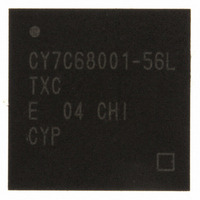
CY7C68001-56LTXC Cypress Semiconductor Corp, CY7C68001-56LTXC Datasheet - Page 14

CY7C68001-56LTXC
Manufacturer Part Number
CY7C68001-56LTXC
Description
IC USB EZ-USB SX2 HS 56VQFN
Manufacturer
Cypress Semiconductor Corp
Series
CY7Cr
Type
USBr
Specifications of CY7C68001-56LTXC
Protocol
USB 2.0
Voltage - Supply
3 V ~ 3.6 V
Mounting Type
Surface Mount
Package / Case
56-VQFN Exposed Pad, 56-HVQFN, 56-SQFN, 56-DHVQFN
Lead Free Status / RoHS Status
Lead free / RoHS Compliant
Number Of Drivers/receivers
-
Lead Free Status / Rohs Status
Lead free / RoHS Compliant
Other names
428-2932
Available stocks
Company
Part Number
Manufacturer
Quantity
Price
Part Number:
CY7C68001-56LTXC
Manufacturer:
CYPRESS/赛普拉斯
Quantity:
20 000
3.7.5
The FIFO flags are FLAGA, FLAGB, FLAGC, and FLAGD. These FLAGx pins report the status of the FIFO selected by the
FIFOADR[2:0] pins. At reset, these pins are configured to report the status of the following:
The FIFO flags can either be indexed or fixed. Fixed flags report the status of a particular FIFO regardless of the value on the
FIFOADR [2:0] pins. Indexed flags report the status of the FIFO selected by the FIFOADR [2:0]pins.
3.7.6
By default, FLAGA is the Programmable Flag (PF) for the endpoint being pointed to by the FIFOADR[2:0] pins. For EP2 and EP4,
the default endpoint configuration is BULK, OUT, 512, 2x, and the PF pin asserts when the entire FIFO has greater than/equal
to 512 bytes. For EP6 and EP8, the default endpoint configuration is BULK, IN, 512, 2x, and the PF pin asserts when the entire
FIFO has less than/equal to 512 bytes. In other words, EP6/8 report a half-empty state, and EP2/4 report a half-full state. The
polarity of the programmable flag is set to active low and cannot be altered.
3.7.7
Each FIFO’s programmable-level flag (PF) asserts when the FIFO reaches a user-defined fullness threshold. That threshold is
configured as follows:
3.7.8
An address of [1 0 0] on FIFOADR [2:0] will select the command interface. The command interface is used to write to and read
from the SX2 registers and the Endpoint 0 buffer, as well as the descriptor RAM. Command read and write transactions occur
over FD[7:0] only. Each byte written to the SX2 is either an address or a data byte, as determined by bit7. If bit7 = 1, then the
byte is considered an address byte. If bit7 = 0, then the byte is considered a data byte. If bit7 = 1, then bit6 determines whether
the address byte is a read request or a write request. If bit6 = 1, then the byte is considered a read request. If bit6 = 0 then the
byte is considered a write request. Bits [5:0] hold the register address of the request. The format of the command address byte
is shown in Table 3-4.
Table 3-4. Command Address Byte
Each Write request is followed by two or more data bytes. If another address byte is received before both data bytes are received,
the SX2 ignores the first address and any incomplete data transfers. The format for the data bytes is shown in Table 3-5 and
Table 3-6. Some registers take a series of bytes. Each byte is transferred using the same protocol.
Table 3-5. Command Data Byte One
Table 3-6. Command Data Byte Two
The first command data byte contains the upper nibble of data, and the second command byte contains the lower nibble of data.
Note:
Document #: 38-08013 Rev. *B
1. For OUT packets: The threshold is stored in PFC12:0. The PF is asserted when the number of bytes in the entire FIFO is less
2. For IN packets, with PKTSTAT = 1: The threshold is stored in PFC9:0. The PF is asserted when the number of bytes written
3. For IN packets, with PKTSTAT = 0: The threshold is stored in two parts: PKTS2:0 holds the number of committed packets, and
3.
• FLAGA reports the status of the programmable flag.
• FLAGB reports the status of the full flag.
• FLAGC reports the status of the empty flag.
• FLAGD defaults to the CS# function.
than/equal to (DECIS = 0) or greater than/equal to (DECIS = 1) the threshold.
into the current packet in the FIFO is less than/equal to (DECIS = 0) or greater than/equal to (DECIS = 1) the threshold.
PFC9:0 holds the number of bytes in the current packet. The PF is asserted when the FIFO is at or less full than (DECIS = 0),
or at or more full than (DECIS = 1), the threshold.
Address/Data#
In indexed mode, the value of the FLAGx pins is indeterminate except when addressing a FIFO (FIFOADR[2:0]={000,001,010,011}).
Bit 7
Bit 7
Bit 7
0
0
FIFO Flag Pins Configuration
Default FIFO Programmable Flag Set-up
FIFO Programmable Flag (PF) Set-up
Command Protocol
Bit 6
Read/Write#
Bit 6
X
X
Bit 6
Bit 5
Bit 5
X
X
Bit 5
A5
Bit 4
Bit 4
X
X
Bit 4
A4
Bit 3
Bit 3
D3
D7
Bit 3
A3
Bit 2
Bit 2
D2
D6
Bit 2
A2
[3]
Bit 1
Bit 1
D1
D5
Bit 1
A1
CY7C68001
Page 14 of 50
Bit 0
Bit 0
Bit 0
D0
D4
A0


