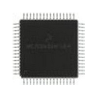
MC68HC908LD60IFU Freescale Semiconductor, MC68HC908LD60IFU Datasheet - Page 217

MC68HC908LD60IFU
Manufacturer Part Number
MC68HC908LD60IFU
Description
Manufacturer
Freescale Semiconductor
Datasheet
1.MC68HC908LD60IFU.pdf
(292 pages)
Specifications of MC68HC908LD60IFU
Cpu Family
HC08
Device Core Size
8b
Frequency (max)
6MHz
Program Memory Type
Flash
Program Memory Size
60KB
Total Internal Ram Size
1KB
# I/os (max)
39
Number Of Timers - General Purpose
2
Operating Supply Voltage (typ)
3.3V
Operating Supply Voltage (max)
3.6V
Operating Supply Voltage (min)
3V
On-chip Adc
6-chx8-bit
Instruction Set Architecture
CISC
Operating Temp Range
0C to 85C
Operating Temperature Classification
Commercial
Mounting
Surface Mount
Pin Count
64
Package Type
PQFP
Lead Free Status / Rohs Status
Compliant
Available stocks
Company
Part Number
Manufacturer
Quantity
Price
- Current page: 217 of 292
- Download datasheet (4Mb)
16.5.2 Sync Signal Counters
16.5.3 Polarity Controlled HOUT and VOUT Outputs
MC68HC908LD60
Freescale Semiconductor
—
Rev. 1.1
There are two counters: a 13-bit horizontal frequency counter to count
the number of horizontal sync pulses within a 32ms or 8ms period; and
a 13-bit vertical frequency counter to count the number of system clock
cycles between two vertical sync pulses. These two data can be read by
the CPU to check the signal frequencies and to determine the video
mode.
The 13-bit vertical frequency register encompasses vertical frequency
range from approximately 15Hz to 128kHz. Due to the asynchronous
timing between the incoming VSYNC signal and internal system clock,
there will be ±1 count error on reading the Vertical Frequency Registers
(VFRs) for the same vertical frequency.
The horizontal counter counts the pulses on HSYNC pin input, and is
uploaded to the Hsync Frequency Registers (HFRs) every 32.768ms or
8.192ms.
The processed sync signals are output on HOUT and VOUT when the
corresponding bits in Configuration Register 0 ($0069) are set. The
signal to these output pins depend on SOUT and COMP bits (see
16-2), with polarity controlled by ATPOL, HINVO, and VINVO bits as
shown in
SOUT
1
0
0
Table
COMP
X
0
1
16-3.
Sync Processor
Table 16-2. Sync Output Control
Free-running video mode output
Sync outputs follow sync inputs VSYNC and HSYNC
respectively, with polarity correction shown in
HOUT follows the composite sync input and VOUT is the
extracted Vsync (3 to 14µs delay to composite input), with
polarity correction shown in
VOUT and HOUT
Sync Outputs:
Table
16-3.
Functional Blocks
Sync Processor
Technical Data
Table
Table
16-3.
217
Related parts for MC68HC908LD60IFU
Image
Part Number
Description
Manufacturer
Datasheet
Request
R
Part Number:
Description:
Manufacturer:
Freescale Semiconductor, Inc
Datasheet:
Part Number:
Description:
Manufacturer:
Freescale Semiconductor, Inc
Datasheet:
Part Number:
Description:
Manufacturer:
Freescale Semiconductor, Inc
Datasheet:
Part Number:
Description:
Manufacturer:
Freescale Semiconductor, Inc
Datasheet:
Part Number:
Description:
Manufacturer:
Freescale Semiconductor, Inc
Datasheet:
Part Number:
Description:
Manufacturer:
Freescale Semiconductor, Inc
Datasheet:
Part Number:
Description:
Manufacturer:
Freescale Semiconductor, Inc
Datasheet:
Part Number:
Description:
Manufacturer:
Freescale Semiconductor, Inc
Datasheet:
Part Number:
Description:
Manufacturer:
Freescale Semiconductor, Inc
Datasheet:
Part Number:
Description:
Manufacturer:
Freescale Semiconductor, Inc
Datasheet:
Part Number:
Description:
Manufacturer:
Freescale Semiconductor, Inc
Datasheet:
Part Number:
Description:
Manufacturer:
Freescale Semiconductor, Inc
Datasheet:
Part Number:
Description:
Manufacturer:
Freescale Semiconductor, Inc
Datasheet:
Part Number:
Description:
Manufacturer:
Freescale Semiconductor, Inc
Datasheet:
Part Number:
Description:
Manufacturer:
Freescale Semiconductor, Inc
Datasheet:


