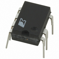
PKS604PN Power Integrations, PKS604PN Datasheet

PKS604PN
Specifications of PKS604PN
Available stocks
Related parts for PKS604PN
PKS604PN Summary of contents
Page 1
... IC to latch off whenever a fault activates the auto-restart function, and to be reset quickly after AC power is removed. Power Integrations’ EcoSmart designed around the PeakSwitch family members to consume <300 mW of no-load power and to meet harmonized energy efficiency standards such as the California Energy Commission (CEC), EU and ENERGY STAR ...
Page 2
AN-41 Scope This application note is intended for engineers designing an isolated AC-DC flyback power supply using the PeakSwitch family of devices. It provides guidelines to enable the engineer to quickly select key components and also complete a suitable transformer ...
Page 3
Step-by-Step Transformer Design Procedure Introduction PeakSwitch devices have current limit values that allow the supply to deliver the specified peak power given in the power table. With sufficient heatsinking, these power levels could be provided continuously. However, PeakSwitch is optimized for use ...
Page 4
AN-41 Line Frequency for universal or 100/115 VAC input for single 230 VAC input. For half-wave rectification use f input enter the voltage directly into Cells B55 and B56. Nominal Output Voltage, V (V) ...
Page 5
DC INPUT VOLTAGE PARAMETERS VMIN VMAX Figure 4. DC Input Voltage Parameters Showing Grey Override Cells for DC Input Designs. Step 2 – Enter PeakSwitch Variables: PeakSwitch Device CLO P(STEADY STATE) Select the correct PeakSwitch device Refer to ...
Page 6
AN-41 be used, as the V is reduced from 135 V, and/or in designs OR with low effective (primary and reflected secondary) leakage inductance values. Ripple to Peak Current Ratio (STEADYSTATE) Below a value of 1, indicating continuous ...
Page 7
Figure 8 provides an illustration of the difference between transient and steady state shows a series of drain current P waveforms for a design that does not meet K limits. In region (a) the K is stable ...
Page 8
AN-41 Step 5 – Choose Core and Bobbin Based on Output Power, and Enter BW Core effective cross-sectional area Core effective path length (cm). E Core ungapped effective inductance, A Bobbin width, BW: (mm) Tape margin width equal to half the total ...
Page 9
Primary Inductance Tolerance, L P_TOLERANCE This is the assumed primary inductance tolerance. A value of 12% is used by default. However, if specific information is known from the transformer vendor, then this may be entered in the grey override cell. ...
Page 10
AN-41 TRANSFORMER SECONDARY DESIGN PARAMETERS (MULTIPLE OUTPUTS) 1st output VO1 IO1 PO1 VD1 NS1 ISRMS1 IRIPPLE1 PIVS1 Recommended Diodes CMS1 AWGS1 DIAS1 ODS1 2nd output VO2 IO2 PO2 VD2 NS2 ISRMS2 IRIPPLE2 PIVS2 Recommended Diode CMS2 AWGS2 DIAS2 ODS2 3rd ...
Page 11
AC input. Referring to Figure 1, the fast AC reset circuit is comprised of D5, C7, R5 and R6. The incoming AC is rectified by D5 ...
Page 12
AN- fast or an ultra-fast recovery type with a reverse recovery time <500 ns. Under no circumstances should a slow recovery rectifier diode be used. The high dissipation that may result during startup or an output short circuit ...
Page 13
Many capacitor manufacturers provide factors that increase the ripple current rating as the capacitor operating temperature is reduced from its data sheet maximum value. This should be considered in order to ensure that the capacitor is not oversized. ESR Specification ...
Page 14
AN- that it does not respond to the cycle-by-cycle output FB2 ripple voltage. AC feedback is provided directly through the optocoupler with C increasing the gain. FB1 If necessary, a post filter (L and C ) can ...
Page 15
Figure 16. Effect of On-Time Extension Operation During Line Brown-Out. (A) Without On-Time Extension Regulation is Lost. (B) With On-Time Regulation is Maintained. If the EN/UV pin has not been pulled low for 750 µs to 1.2 ms and ...
Page 16
... For the latest updates, visit our website: www.powerint.com Power Integrations reserves the right to make changes to its products at any time to improve reliability or manufacturability. Power Integrations does not assume any liability arising from the use of any device or circuit described herein. POWER INTEGRATIONS MAKES NO WARRANTY HEREIN AND SPECIFICALLY DISCLAIMS ALL WARRANTIES INCLUDING, WITHOUT LIMITATION, THE IMPLIED WARRANTIES OF MERCHANTABILITY, FITNESS FOR A PARTICULAR PURPOSE, AND NON-INFRINGEMENT OF THIRD PARTY RIGHTS ...


