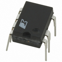
PKS604PN Power Integrations, PKS604PN Datasheet - Page 2

PKS604PN
Manufacturer Part Number
PKS604PN
Description
IC OFFLINE SWIT OTP OCP HV 8DIP
Manufacturer
Power Integrations
Series
PeakSwitch®r
Specifications of PKS604PN
Mfg Application Notes
PeakSwitch Design Guide AppNote
Output Isolation
Isolated
Frequency Range
250 ~ 304kHz
Voltage - Output
700V
Power (watts)
56W
Operating Temperature
-40°C ~ 150°C
Package / Case
8-DIP (0.300", 7.62mm), 7 Leads
Output Voltage
12 V
Input / Supply Voltage (max)
265 VAC
Input / Supply Voltage (min)
85 VAC
Duty Cycle (max)
65 %
Switching Frequency
47 KHz
Supply Current
25 uA
Operating Temperature Range
- 40 C to + 150 C
Mounting Style
Through Hole
For Use With
596-1126 - KIT DESIGN ACC PEAKSWITCH FAMILY
Lead Free Status / RoHS Status
Lead free / RoHS Compliant
Other names
596-1117-5
Available stocks
Company
Part Number
Manufacturer
Quantity
Price
Company:
Part Number:
PKS604PN
Manufacturer:
POWER
Quantity:
15 000
Part Number:
PKS604PN
Manufacturer:
POWER
Quantity:
20 000
Scope
This application note is intended for engineers designing an
isolated AC-DC flyback power supply using the PeakSwitch
family of devices. It provides guidelines to enable the engineer
to quickly select key components and also complete a suitable
transformer design. To simplify the task, this application note
refers directly to the PI Xls design spreadsheet that is part of
the PI Expert™ power supply design software suite.
In addition to this application note, the reader may also find the
PeakSwitch Reference Design Kit (RDK) (the RDK contains
an engineering prototype board, engineering report and device
sample) useful as an example of a working power supply. Further
details on downloading PI Expert, obtaining an RDK and updates
to this document can be found at www.powerint.com.
Quick Start
Readers can use the following information to quickly design a
transformer and select the components for a first prototype. Only
the information described below needs to be entered into the
PI Xls spreadsheet; other parameters will be automatically
selected by the spreadsheet, based on a typical design. References
to spreadsheet cell locations are provided in square brackets
[cell reference].
• Enter AC input voltage range VAC
• Enter nominal output voltage V
• Enter minimum output voltage at peak load assuming an
• Enter maximum output current at peak load or maximum
• Enter continuous (average) output power [B9]
• Enter efficiency estimate:
• Enter loss allocation factor Z [B12]:
• Enter C
Rev. E 02/07
minimum line frequency f
output drop is acceptable (if applicable) [B7]
continuous load as applicable [B5]
2
0.7 for universal input voltage (85-265 VAC) or single
100/115 VAC (85-132 VAC) line voltage, and 0.75 for
single 230 VAC (185-265 VAC) line voltage designs.
Adjust the efficiency estimate accordingly, after
measuring the efficiency of the first prototype-board at
peak load and VAC
0.65 for typical application (adjust the number
accordingly after first proto-board evaluation)
IN
input capacitance [B14]:
AN-41
MIN
L
. [B11]
[B3, B4, B5]
O
[B6]
MIN
, VAC
MAX
and
• Select PeakSwitch from drop down list or enter directly
Select the device in the table below according to output power
and line input voltage.
Table 1. Output Power Table (See Data Sheet for Notes 1, 2 and 3).
• Enter V
• Enter core type (if desired) from drop down menu [B43]:
A suggested core size will be selected automatically by the
spreadsheet if none is entered.
• Build transformer
• Select key components (see Steps 5 through 10)
• Build prototype, test and iterate the design as necessary,
PKS603 P
PKS604 P
PKS604 Y/F
PKS605 P
PKS605 Y/F
PKS606 P
PKS606 Y/F
PKS607 Y/F
[B17]:
entering measured values into the spreadsheet where
estimates were initially used (e.g. efficiency, V
PRODUCT
[B25]:
0.5 V for Schottky diode
0.7 V for PN diode
Use 2 µF/W
(100/115 VAC) line voltage, if output voltage droop
is acceptable, or 3 µF/W
unacceptable.
Use 1 µF/W
265 VAC) high-line voltage.
D
– forward voltage drop of the output diode
OUTPUT POWER TABLE
3
Adapter
Cont.
PK
230 VAC ±15%
PK
13 W
23 W
35 W
31 W
46 W
35 W
68 W
75 W
for universal (85-265 VAC) or single
single 230 VAC for a single (185-
1
Adapter
117 W
126 W
Peak
32 W
56 W
56 W
60 W
79 W
66 W
PK
if output voltage droop is
2
Adapter
Cont.
16 W
23 W
21 W
30 W
25 W
45 W
50 W
9 W
85-265 VAC
1
MIN
Adapter
)
Peak
25 W
44 W
44 W
44 W
58 W
46 W
86 W
93 W
2


