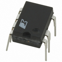
PKS604PN Power Integrations, PKS604PN Datasheet - Page 3

PKS604PN
Manufacturer Part Number
PKS604PN
Description
IC OFFLINE SWIT OTP OCP HV 8DIP
Manufacturer
Power Integrations
Series
PeakSwitch®r
Specifications of PKS604PN
Mfg Application Notes
PeakSwitch Design Guide AppNote
Output Isolation
Isolated
Frequency Range
250 ~ 304kHz
Voltage - Output
700V
Power (watts)
56W
Operating Temperature
-40°C ~ 150°C
Package / Case
8-DIP (0.300", 7.62mm), 7 Leads
Output Voltage
12 V
Input / Supply Voltage (max)
265 VAC
Input / Supply Voltage (min)
85 VAC
Duty Cycle (max)
65 %
Switching Frequency
47 KHz
Supply Current
25 uA
Operating Temperature Range
- 40 C to + 150 C
Mounting Style
Through Hole
For Use With
596-1126 - KIT DESIGN ACC PEAKSWITCH FAMILY
Lead Free Status / RoHS Status
Lead free / RoHS Compliant
Other names
596-1117-5
Available stocks
Company
Part Number
Manufacturer
Quantity
Price
Company:
Part Number:
PKS604PN
Manufacturer:
POWER
Quantity:
15 000
Part Number:
PKS604PN
Manufacturer:
POWER
Quantity:
20 000
Step-by-Step Transformer Design
Procedure
Introduction
PeakSwitch devices have current limit values that allow the
supply to deliver the specified peak power given in the power
table. With sufficient heatsinking, these power levels could
be provided continuously. However, PeakSwitch is optimized
for use in applications that demand short duration, high peak
power, while delivering a significantly lower continuous power.
Typical peak-to-continuous ratios would be P
The high switching frequency of PeakSwitch allows a small core
size to deliver the peak power but the short duration prevents the
transformer windings from overheating and reduces heatsinking
requirement for the device.
As the average power increases, based on the measured transformer
temperature, it may be necessary to select a larger transformer so
that the current density of its windings can be decreased.
The power table provides some guidance for peak and
continuous (average) power levels in sealed adapters, although
specific applications may vary. For example, if the peak power
condition is of very low duty cycle, such as a two-second peak
occurring at power up to accelerate a hard disk drive, then the
temperature rise of the transformer is a function of the continuous
power. However, if the peak power occurs every 200 ms for
50 ms, then peak power heating effects would need to be considered.
Figure 2 shows how to calculate the average power requirements
for a design with two different peak load conditions.
Where P
represent the durations of each peak power condition and T is
the period of one cycle of the pulsed load condition.
Figure 3. Application Variable Section of PeakSwitch Design Spreadsheet.
ENTER APPLICATION VARIABLES
VACMIN
VACMAX
fL
Nominal Output Voltage (VO)
Maximum Output Current (IO)
Minimum Output Voltage at Peak Load
Continuous Power
Peak Power
n
Z
tC Estimate
CIN
x
represents the different output power conditions, Dt
P
d
AVE
1
=
=
D
T
P
t
1
1
,
+
d
2
(
=
P
3
-
D
T
t
P
2
1
)
$
d
1
+
24.00
47.00
(
P
0.75
6.00
0.70
3.00
265
2
85
50
-
P
1
)
$
PEAK
d
2
≥ 2 × P
AVE
x
.
24.00
18.00
6.00
0.60
47
Volts
Volts
Hertz
Volts
Amps
Volts
Watts
Watts
mSeconds
uFarads
Power (W)
Figure 2. Continuous (Average) Output Power Calculation Example.
The design procedure requires both peak and continuous powers
to be specified. The peak power is used to select the PeakSwitch
device and design the transformer for power delivery at minimum
input line voltage while continuous power (or average power if
the peak load is periodic) is used for thermal design and may
affect the size of the transformer and the heat sink.
Step 1. Enter Application Variables VAC
f
Table 2. Standard Worldwide Input Line Voltage Ranges.
Determine the input voltage range from Table 2.
L
P
P
P
, V
3
2
1
Nominal Input Voltage
O
, I
O
, V
AN41 Example
Minimum AC Input Voltage
Maximum AC Input Voltage
AC Mains Frequency
Nominal Output Voltage (at continuous power)
Power Supply Output Current (corresponding to peak power)
Minimum Output Voltage at Peak Power (Assuming output droop
during peak load)
Continuous Output Power
Peak Output Power
Efficiency Estimate at output terminals and at peak load. Enter
0.7 if no better data available
Loss Allocation Factor (Z = Secondary side losses / Total losses)
Bridge Rectifier Conduction Time Estimate
Input Capacitance
Universal
100/115
(VAC)
O
at Peak Load, h, Z, t
230
∆t
1
T
VAC
AN-41
195
85
85
C
∆t
, C
2
MIN
IN
MIN
VAC
, VAC
132
265
265
Rev. E 02/07
MAX
Time (t)
3
MAX
,


