PKS604PN Power Integrations, PKS604PN Datasheet - Page 12
PKS604PN
Manufacturer Part Number
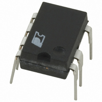
PKS604PN
Description
IC OFFLINE SWIT OTP OCP HV 8DIP
Manufacturer
Power Integrations
Series
PeakSwitch®r
Specifications of PKS604PN
Mfg Application Notes
PeakSwitch Design Guide AppNote
Output Isolation
Isolated
Frequency Range
250 ~ 304kHz
Voltage - Output
700V
Power (watts)
56W
Operating Temperature
-40°C ~ 150°C
Package / Case
8-DIP (0.300", 7.62mm), 7 Leads
Output Voltage
12 V
Input / Supply Voltage (max)
265 VAC
Input / Supply Voltage (min)
85 VAC
Duty Cycle (max)
65 %
Switching Frequency
47 KHz
Supply Current
25 uA
Operating Temperature Range
- 40 C to + 150 C
Mounting Style
Through Hole
For Use With
596-1126 - KIT DESIGN ACC PEAKSWITCH FAMILY
Lead Free Status / RoHS Status
Lead free / RoHS Compliant
Other names
596-1117-5
Available stocks
Company
Part Number
Manufacturer
Quantity
Price
Company:

Part Number:
PKS604PN
Manufacturer:
POWER
Quantity:
15 000
Part Number:
PKS604PN
Manufacturer:
POWER
Quantity:
20 000


be a fast or an ultra-fast recovery type with a reverse recovery
time <500 ns. Under no circumstances should a slow recovery
rectifier diode be used. The high dissipation that may result
during startup or an output short circuit can cause failure of the
diode. Resistor R4 dampens ringing for reduced EMI.
Supplies using different devices in the PeakSwitch family will
have different peak primary current, leakage inductances and
leakage energy. Therefore, C5 and R3 should be optimized for
each design. As a general rule, minimize the value of capacitor
C5 and maximize the value of resistor R3.
Step 10 – Select Output Rectifier Diode
For each output, use the values of peak inverse voltage (V
and output current (I
to select the output diodes. Table 4 shows some commonly
available types.
V
Stress Parameters section of the spreadsheet and Transformer
Secondary Design Parameters (Multiple Outputs).
Table 5. Zener Feedback Arrangement and Typical Component Values.
Rev. E 02/07
12
R
Output Voltage
≥ 1.25 × PIVS: where PIVS is taken from the Voltage
(V)
12
18
24
30
5
8
AN-41
O
) provided in the design spreadsheet
Zener Value,
VR
4.3
7.5
16
22
28
FB
11
(V)
Feedback Bias
C
Resistor, R
OUT
(kW)
U
1
FB1
R
FB1
BIAS
R
)
D
VR
FB
FB
Resistor, R
I
is the average output current. Depending on the thermal rise
and duration of the peak load condition, it may be necessary to
increase the diode current rating once a prototype has been built.
This also applies to the amount of heatsinking required.
Step 11 – Select Output Capacitor
Ripple Current Rating
The spreadsheet calculates the output capacitor ripple current
at peak load. Therefore the actual rating of the capacitor will
depend on the peak to average power ratio of the design. For
a conservative design, select the output capacitor(s) such that
the ripple rating is greater than the calculated value, I
from the spreadsheet, calculated at the peak load condition.
However in designs with high peak to continuous (average)
power ratios, the capacitor rating can be reduced based on the
measured temperature rise under worst-case load and ambient
temperature. If a suitable individual capacitor cannot be found,
then two or more capacitors may be used in parallel to achieve a
combined ripple current rating equal to the sum of the individual
capacitor ratings.
Opto Series
D
≥ 2 × I
R
C
L
BIAS
FB1
PF
220
(W)
O
: where I
FB1
PI-4338-031606
D
C
is the rated DC current of the diode and I
Capacitor, C
PF
Feedback
+V
RTN
OUT
(nF)
100
FB1
D
Series Diode
FB
Required?
Yes
No
RIPPLE
O
Related parts for PKS604PN
Image
Part Number
Description
Manufacturer
Datasheet
Request
R

Part Number:
Description:
SOP-16
Manufacturer:
Power Integrations
Datasheet:
Part Number:
Description:
DIP8
Manufacturer:
Power Integrations
Datasheet:
Part Number:
Description:
TO-263
Manufacturer:
Power Integrations
Datasheet:
Part Number:
Description:
TO-263
Manufacturer:
Power Integrations
Datasheet:
Part Number:
Description:
Manufacturer:
Power Integrations
Datasheet: