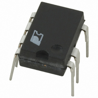
PKS604PN Power Integrations, PKS604PN Datasheet - Page 15

PKS604PN
Manufacturer Part Number
PKS604PN
Description
IC OFFLINE SWIT OTP OCP HV 8DIP
Manufacturer
Power Integrations
Series
PeakSwitch®r
Specifications of PKS604PN
Mfg Application Notes
PeakSwitch Design Guide AppNote
Output Isolation
Isolated
Frequency Range
250 ~ 304kHz
Voltage - Output
700V
Power (watts)
56W
Operating Temperature
-40°C ~ 150°C
Package / Case
8-DIP (0.300", 7.62mm), 7 Leads
Output Voltage
12 V
Input / Supply Voltage (max)
265 VAC
Input / Supply Voltage (min)
85 VAC
Duty Cycle (max)
65 %
Switching Frequency
47 KHz
Supply Current
25 uA
Operating Temperature Range
- 40 C to + 150 C
Mounting Style
Through Hole
For Use With
596-1126 - KIT DESIGN ACC PEAKSWITCH FAMILY
Lead Free Status / RoHS Status
Lead free / RoHS Compliant
Other names
596-1117-5
Available stocks
Company
Part Number
Manufacturer
Quantity
Price
Company:
Part Number:
PKS604PN
Manufacturer:
POWER
Quantity:
15 000
Part Number:
PKS604PN
Manufacturer:
POWER
Quantity:
20 000
Figure 16. Effect of On-Time Extension Operation During Line Brown-Out. (A) Without On-Time Extension Regulation is Lost. (B) With
If the EN/UV pin has not been pulled low for 750 µs to
1.2 ms and every enabled switching cycle has terminated
because DMAX was reached (instead of current limit), the on-
time extension function is enabled. The maximum duty cycle
limit is then disabled and switching cycles are terminated by
current limit alone. Therefore, the MOSFET on time is only
determined by the time for the primary current to reach current
limit. The off time of the MOSFET remains fixed at (1-D
1/f
frequency. Once the EN/UV pin has been pulled low, indicating
the output is again in regulation, on-time extension is disabled,
and the MOSFET on time is terminated either by current limit
or maximum duty cycle.
Since on-time extension is only enabled after the EN/UV pin
has not been pulled low for up to 1.2 ms, the output may also
have been out of regulation for that duration. Therefore, verify
that the output voltage ripple is acceptable during instances of
on-time extension.
Other Information
Adaptive Current Limit
PeakSwitch incorporates an adaptive current limit function.
When the current-limit state machine has the current limit set
to 100% and an enabled switching cycle that follows a disabled
switching cycle reaches current limit before DMAX, the adaptive
current limit function reduces the current limit by about 10%.
Once a cycle is skipped, the current limit is returned to the 100%
value. This simplifies compliance with power limited source
safety testing by limiting the overload power at high line.
S
, where D
(A)
On-Time Regulation is Maintained.
MAX
is the maximum duty cycle and f
S
the switching
MAX
(B)
) ×
Layout Guidelines
See data sheet for layout guidelines.
Quick Design Checklist
See data sheet for quick design checklist.
Figure 17. Example of Adaptive Current Limit.
I
DRAIN
0.5 A/div
10%
AN-41
All 50 ms/div
V
I
V
DRAIN
AC
OUT
(350 V/div)
(15 V/div)
(2 A/div)
5 µs/div
Rev. E 02/07
15


