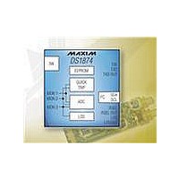
DS1874T+ Maxim Integrated Products, DS1874T+ Datasheet - Page 68

DS1874T+
Manufacturer Part Number
DS1874T+
Description
IC CTLR SFP+ ANLG LDD 28-TQFN
Manufacturer
Maxim Integrated Products
Type
Laser Diode Controllerr
Datasheet
1.DS1874TTR.pdf
(88 pages)
Specifications of DS1874T+
Number Of Channels
1
Voltage - Supply
2.85 V ~ 3.9 V
Current - Supply
2.5mA
Operating Temperature
-40°C ~ 95°C
Package / Case
28-WFQFN Exposed Pad
Mounting Type
Surface Mount
Number Of Outputs
5
Duty Cycle (max)
50 %
Output Voltage
0 V to 3.9 V
Mounting Style
SMD/SMT
Switching Frequency
0 KHz to 400 KHz
Operating Supply Voltage
2.85 V to 3.9 V
Supply Current
2.5 mA to 10 mA
Maximum Operating Temperature
+ 95 C
Fall Time
300 ns
Minimum Operating Temperature
- 40 C
Rise Time
300 ns
Synchronous Pin
Yes
Lead Free Status / RoHS Status
Lead free / RoHS Compliant
Other names
90-1874T+000
Table 02h, Register BAh: RESERVED
SFP+ Controller with Digital LDD Interface
Table 02h, Register BBh: ISTEP
Table 02h, Register BCh: HTXP
68
______________________________________________________________________________________
BBh
BCh
FACTORY DEFAULT
READ ACCESS
WRITE ACCESS
MEMORY TYPE
This register is reserved.
FACTORY DEFAULT
READ ACCESS
WRITE ACCESS
MEMORY TYPE
The initial step value used at power-on or after a TXD pulse to control the BIAS register. At startup, this value plus
2
At that time, a binary search is used to complete the startup of the APC closed loop. If the resulting math operation is
greater than IBIASMAX (Table 02h, Register EEh), the result is not loaded into the BIAS register, but the binary
search is begun to complete the initial search for APC. During startup, the BIAS register steps causing a higher bias
value than IBIASMAX do not create the BIAS MAX alarm. The BIAS MAX alarm detection is enabled at the end of the
binary search.
FACTORY DEFAULT
READ ACCESS
WRITE ACCESS
MEMORY TYPE
Fast-comparison DAC threshold adjust for high TXP. This value is added to the APC DAC value recalled from
Table 06h. If the sum is greater than 0xFF, 0xFF is used. Comparisons greater than V
V
0
MON2
= 1 is continuously added to the BIAS register value until the APC feedback (MON2) is greater than its threshold.
BIT 7
BIT 7
2
2
8
7
, create a TXP HI alarm. The same ranging applied to the APC DAC should be used here.
2
2
7
6
00h
PW2 or (PW1 and RWTBL246) or (PW1 and RTBL246)
PW2 or (PW1 and RWTBL246)
Nonvolatile (SEE)
00h
PW2 or (PW1 and RWTBL246) or (PW1 and RTBL246)
PW2 or (PW1 and RWTBL246)
Nonvolatile (SEE)
00h
PW2 or (PW1 and RWTBL246) or (PW1 and RTBL246)
PW2 or (PW1 and RWTBL246)
Nonvolatile (SEE)
2
2
6
5
V
HTXP
=
Full Scale
2
255
2
5
4
(
HTXP + APC DAC
2
2
4
3
)
2
2
3
2
HTXP
2
2
2
1
, compared against
BIT 0
BIT 0
2
2
1
0


