DS1874T+ Maxim Integrated Products, DS1874T+ Datasheet - Page 71
DS1874T+
Manufacturer Part Number
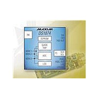
DS1874T+
Description
IC CTLR SFP+ ANLG LDD 28-TQFN
Manufacturer
Maxim Integrated Products
Type
Laser Diode Controllerr
Datasheet
1.DS1874TTR.pdf
(88 pages)
Specifications of DS1874T+
Number Of Channels
1
Voltage - Supply
2.85 V ~ 3.9 V
Current - Supply
2.5mA
Operating Temperature
-40°C ~ 95°C
Package / Case
28-WFQFN Exposed Pad
Mounting Type
Surface Mount
Number Of Outputs
5
Duty Cycle (max)
50 %
Output Voltage
0 V to 3.9 V
Mounting Style
SMD/SMT
Switching Frequency
0 KHz to 400 KHz
Operating Supply Voltage
2.85 V to 3.9 V
Supply Current
2.5 mA to 10 mA
Maximum Operating Temperature
+ 95 C
Fall Time
300 ns
Minimum Operating Temperature
- 40 C
Rise Time
300 ns
Synchronous Pin
Yes
Lead Free Status / RoHS Status
Lead free / RoHS Compliant
Other names
90-1874T+000


Table 02h, Register C1h: PW_ENB
C1h
SFP+ Controller with Digital LDD Interface
FACTORY DEFAULT
READ ACCESS
WRITE ACCESS
MEMORY TYPE
RWTBL46
BIT 7
BIT 7
BIT 6
BIT 5
BIT 4
BIT 3
BIT 2
BIT 1
BIT 0
______________________________________________________________________________________
RWTBL46: Read and Write Tables 04h, 06h
0 = (Default) Read and write access for PW2 only.
1 = Read and write access for both PW1 and PW2.
RTBL1C: Read Table 01h or Table 05h, Registers F8h–FFh. Table address is dependent on MASK
bit (Table 02h, Register 89h).
0 = (Default) Read access for PW2 only.
1 = Read access for PW1 and PW2.
RTBL2: Read Table 02h except for PW1 value locations (Table 02h, Registers B0h–B3h)
0 = (Default) Read access for PW2 only.
1 = Read access for PW1 and PW2.
RTBL1A: Read Table 01h, Registers 80h–BFh
0 = (Default) Read access for PW2 only.
1 = Read access for PW1 and PW2.
RTBL1B: Read Table 01h, Registers C0h–F7h
0 = (Default) Read access for PW2 only.
1 = Read access for PW1 and PW2.
WPW1: Write Register PW1 (Table 02h, Registers B0h–B3h). For security purposes these registers
are not readable.
0 = (Default) Write access for PW2 only.
1 = Write access for PW1 and PW2.
WAUXAU: Write Auxiliary Memory, Registers 00h–7Fh. All users can read this area.
0 = Write access for PW2 only.
1 = (Default) Write access for user, PW1 and PW2.
WAUXBU: Write Auxiliary Memory, Registers 80h–FFh
0 = Read and write access for PW2 only.
1 = (Default) Read and write access for user, PW1 and PW2.
RTBL1C
03h
PW2 or (PW1 and RWTBL246) or (PW1 and RTBL246)
PW2 or (PW1 and RWTBL246)
Nonvolatile (SEE)
RTBL2
RTBL1A
RTBL1B
WPW1
WAUXAU
WAUXBU
BIT 0
71
Related parts for DS1874T+
Image
Part Number
Description
Manufacturer
Datasheet
Request
R

Part Number:
Description:
MAX7528KCWPMaxim Integrated Products [CMOS Dual 8-Bit Buffered Multiplying DACs]
Manufacturer:
Maxim Integrated Products
Datasheet:
Part Number:
Description:
Single +5V, fully integrated, 1.25Gbps laser diode driver.
Manufacturer:
Maxim Integrated Products
Datasheet:
Part Number:
Description:
Single +5V, fully integrated, 155Mbps laser diode driver.
Manufacturer:
Maxim Integrated Products
Datasheet:
Part Number:
Description:
VRD11/VRD10, K8 Rev F 2/3/4-Phase PWM Controllers with Integrated Dual MOSFET Drivers
Manufacturer:
Maxim Integrated Products
Datasheet:
Part Number:
Description:
Highly Integrated Level 2 SMBus Battery Chargers
Manufacturer:
Maxim Integrated Products
Datasheet:
Part Number:
Description:
Current Monitor and Accumulator with Integrated Sense Resistor; ; Temperature Range: -40°C to +85°C
Manufacturer:
Maxim Integrated Products
Part Number:
Description:
TSSOP 14/A�/RS-485 Transceivers with Integrated 100O/120O Termination Resis
Manufacturer:
Maxim Integrated Products
Part Number:
Description:
TSSOP 14/A�/RS-485 Transceivers with Integrated 100O/120O Termination Resis
Manufacturer:
Maxim Integrated Products
Part Number:
Description:
QFN 16/A�/AC-DC and DC-DC Peak-Current-Mode Converters with Integrated Step
Manufacturer:
Maxim Integrated Products
Part Number:
Description:
TDFN/A/65V, 1A, 600KHZ, SYNCHRONOUS STEP-DOWN REGULATOR WITH INTEGRATED SWI
Manufacturer:
Maxim Integrated Products
Part Number:
Description:
Integrated Temperature Controller f
Manufacturer:
Maxim Integrated Products
Part Number:
Description:
SOT23-6/I�/45MHz to 650MHz, Integrated IF VCOs with Differential Output
Manufacturer:
Maxim Integrated Products
Part Number:
Description:
SOT23-6/I�/45MHz to 650MHz, Integrated IF VCOs with Differential Output
Manufacturer:
Maxim Integrated Products
Part Number:
Description:
EVALUATION KIT/2.4GHZ TO 2.5GHZ 802.11G/B RF TRANSCEIVER WITH INTEGRATED PA
Manufacturer:
Maxim Integrated Products