C8051F350DK Silicon Laboratories Inc, C8051F350DK Datasheet - Page 135
C8051F350DK
Manufacturer Part Number
C8051F350DK
Description
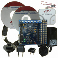
DEV KIT FOR F350/351/352/353
Manufacturer
Silicon Laboratories Inc
Type
MCUr
Specifications of C8051F350DK
Contents
Evaluation Board, Power Supply, USB Cables, Adapter and Documentation
Processor To Be Evaluated
C8051F35x
Interface Type
USB
Silicon Manufacturer
Silicon Labs
Core Architecture
8051
Silicon Core Number
C8051F350
Silicon Family Name
C8051F35x
Lead Free Status / RoHS Status
Contains lead / RoHS non-compliant
For Use With/related Products
C8051F350, 351, 352, 353
Lead Free Status / Rohs Status
Lead free / RoHS Compliant
Other names
336-1083
Available stocks
Company
Part Number
Manufacturer
Quantity
Price
Company:

Part Number:
C8051F350DK
Manufacturer:
SiliconL
Quantity:
8


17.3. Clock Multiplier
The Clock Multiplier generates an output clock which is 4 times the input clock frequency. The Clock Multi-
plier’s input can be selected from the external oscillator, or 1/2 the internal or external oscillators. This pro-
duces three possible outputs: Internal Oscillator x 2, External Oscillator x 2, or External Oscillator x 4. See
Section “17.4. System Clock Selection’ on page 136 for details on system clock selection.
The Clock Multiplier is configured via the CLKMUL register (SFR Definition 17.4). The procedure for con-
figuring and enabling the Clock Multiplier is as follows:
Important Note: When using an external oscillator as the input to the Clock Multiplier, the external
source must be enabled and stable before the Multiplier is initialized. See Section “17.4. System
Clock Selection’ on page 136 for details on selecting an external oscillator source.
Bit7:
Bit6:
Bit5:
Bits4–2: Unused. Read = 000b; Write = don’t care.
Bits1–0: MULSEL: Clock Multiplier Input Select
MULEN
R/W
Bit7
1. Reset the Multiplier by writing 0x00 to register CLKMUL.
2. Select the Multiplier input source via the MULSEL bits.
3. Enable the Multiplier with the MULEN bit (CLKMUL | = 0x80).
4. Delay for >5 µs.
5. Initialize the Multiplier with the MULINIT bit (CLKMUL | = 0xC0).
6. Poll for MULRDY => ‘1’.
MULEN: Clock Multiplier Enable
0: Clock Multiplier disabled.
1: Clock Multiplier enabled.
MULINIT: Clock Multiplier Initialize
This bit should be a ‘0’ when the Clock Multiplier is enabled. Once enabled, writing a ‘1’ to
this bit will initialize the Clock Multiplier. The MULRDY bit reads ‘1’ when the Clock Multiplier
is stabilized.
MULRDY: Clock Multiplier Ready
This read-only bit indicates the status of the Clock Multiplier.
0: Clock Multiplier not ready.
1: Clock Multiplier ready (locked).
These bits select the clock supplied to the Clock Multiplier.
MULINIT MULRDY
R/W
Bit6
SFR Definition 17.4. CLKMUL: Clock Multiplier Control
MULSEL
00
01
10
11
Bit5
R
R/W
Bit4
—
Selected Input Clock
External Oscillator / 2
Internal Oscillator / 2
External Oscillator
RESERVED
Rev. 1.1
R/W
Bit3
—
R/W
Bit2
—
C8051F350/1/2/3
Clock Multipler Output
External Oscillator x 4
External Oscillator x 2
R/W
Internal Oscillator x 2
Bit1
MULSEL
RESERVED
SFR Address:
R/W
Bit0
0xBE
00000000
Reset Value
135
Related parts for C8051F350DK
Image
Part Number
Description
Manufacturer
Datasheet
Request
R

Part Number:
Description:
SMD/C°/SINGLE-ENDED OUTPUT SILICON OSCILLATOR
Manufacturer:
Silicon Laboratories Inc
Part Number:
Description:
Manufacturer:
Silicon Laboratories Inc
Datasheet:
Part Number:
Description:
N/A N/A/SI4010 AES KEYFOB DEMO WITH LCD RX
Manufacturer:
Silicon Laboratories Inc
Datasheet:
Part Number:
Description:
N/A N/A/SI4010 SIMPLIFIED KEY FOB DEMO WITH LED RX
Manufacturer:
Silicon Laboratories Inc
Datasheet:
Part Number:
Description:
N/A/-40 TO 85 OC/EZLINK MODULE; F930/4432 HIGH BAND (REV E/B1)
Manufacturer:
Silicon Laboratories Inc
Part Number:
Description:
EZLink Module; F930/4432 Low Band (rev e/B1)
Manufacturer:
Silicon Laboratories Inc
Part Number:
Description:
I°/4460 10 DBM RADIO TEST CARD 434 MHZ
Manufacturer:
Silicon Laboratories Inc
Part Number:
Description:
I°/4461 14 DBM RADIO TEST CARD 868 MHZ
Manufacturer:
Silicon Laboratories Inc
Part Number:
Description:
I°/4463 20 DBM RFSWITCH RADIO TEST CARD 460 MHZ
Manufacturer:
Silicon Laboratories Inc
Part Number:
Description:
I°/4463 20 DBM RADIO TEST CARD 868 MHZ
Manufacturer:
Silicon Laboratories Inc
Part Number:
Description:
I°/4463 27 DBM RADIO TEST CARD 868 MHZ
Manufacturer:
Silicon Laboratories Inc
Part Number:
Description:
I°/4463 SKYWORKS 30 DBM RADIO TEST CARD 915 MHZ
Manufacturer:
Silicon Laboratories Inc
Part Number:
Description:
N/A N/A/-40 TO 85 OC/4463 RFMD 30 DBM RADIO TEST CARD 915 MHZ
Manufacturer:
Silicon Laboratories Inc
Part Number:
Description:
I°/4463 20 DBM RADIO TEST CARD 169 MHZ
Manufacturer:
Silicon Laboratories Inc