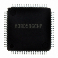
M38D59GCHP#U0 Renesas Electronics America, M38D59GCHP#U0 Datasheet - Page 118

M38D59GCHP#U0
Manufacturer Part Number
M38D59GCHP#U0
Description
IC 740/38D5 MCU QZ-ROM 80LQFP
Manufacturer
Renesas Electronics America
Series
740/38000r
Datasheet
1.M38D58G8FPU0.pdf
(144 pages)
Specifications of M38D59GCHP#U0
Core Processor
740
Core Size
8-Bit
Speed
12.5MHz
Connectivity
SIO, UART/USART
Peripherals
LCD, LED, PWM, WDT
Number Of I /o
59
Program Memory Size
48KB (48K x 8)
Program Memory Type
QzROM
Ram Size
2K x 8
Voltage - Supply (vcc/vdd)
1.8 V ~ 5.5 V
Data Converters
A/D 8x10b
Oscillator Type
Internal
Operating Temperature
-20°C ~ 85°C
Package / Case
80-LQFP
Lead Free Status / RoHS Status
Lead free / RoHS Compliant
Eeprom Size
-
Available stocks
Company
Part Number
Manufacturer
Quantity
Price
- Current page: 118 of 144
- Download datasheet (3Mb)
38D5 Group
Rev.3.04
REJ03B0158-0304
Timing Requirements And Switching Characteristics
Table 42 Power supply circuit characteristics
Table 43 Timing requirements (1)
NOTES:
td(P-R)
t
t
t
t
t
t
t
t
t
t
t
t
t
t
t
t
t
t
t
W
C
WH
WL
C
WH
WL
WH
WL
C
WH
WL
su
h
C
WH
WL
su
h
1. 80 ns in the frequency/2 mode.
2. 32 ns in the frequency/2 mode.
3. When bit 6 of address 001A
(S
(S
(X
(CNTR)
(S
(S
(RESET)
(R
(S
(X
(CNTR)
(INT)
(S
(S
(X
(CNTR)
(INT)
(S
(S
CLK1
CLK2
IN
CLK1
CLK2
Symbol
x
IN2
Divide this value by four when bit 6 of address 001A
IN
CLK1
CLK2
D-S
Symbol
IN
CLK1
CLK2
)
)
)
-S
-R
-S
)
)
CLK1
)
)
CLK2
)
)
IN2
x
(Vcc = 2.7 to 5.5 V, Vss = 0 V, Ta = − 20 to 85 ° C, unless otherwise noted)
(Vcc = 4.0 to 5.5 V, Vss = 0 V, Ta = − 20 to 85 ° C, unless otherwise noted)
D)
)
May 20, 2008 Page 116 of 134
)
)
Reset input “L” pulse width
Main clock input cycle time
Main clock input “H” pulse width
Main clock input “L” pulse width
CNTR
CNTR
CNTR
INT
INT
Serial I/O1 clock input cycle time
Serial I/O1 clock input “H” pulse width
Serial I/O1 clock input “L” pulse width
Serial I/O1 input setup time
Serial I/O1 input hold time
Serial I/O2 clock input cycle time
Serial I/O2 clock input “H” pulse width
Serial I/O2 clock input “L” pulse width
Serial I/O2 input setup time
Serial I/O2 input hold time
Internal power source voltage
stabilizes time at power-on
00
00
, INT
, INT
0
0
0
, CNTR
, CNTR
, CNTR
01
01
Parameter
, INT
, INT
1
1
1
16
input cycle time
input “H” pulse width
input “L” pulse width
10
10
is “1” (clock synchronous).
, INT
, INT
11
11
, INT
, INT
Parameter
2
2
input “H” pulse width
input “L” pulse width
(3)
4.5V ≤ V
4.0V ≤ V
4.5V ≤ V
4.0V ≤ V
4.5V ≤ V
4.0V ≤ V
2.7 ≤ V
Test conditions
(3)
(3)
16
is “0” (UART).
CC
CC
CC
CC
CC
CC
CC
≤ 5.5V
≤ 5.5V
≤ 5.5V
< 4.5V
< 4.5V
< 4.5V
≤ 5.5V
(1)
(2)
(2)
Min.
2
1000
Min.
62.5
125
250
105
105
800
370
370
220
100
400
400
200
200
25
50
25
50
80
80
2
Limits
FLASH MEMORY VERSION
Typ.
Limits
Typ.
Max.
Max.
Unit
ms
Unit
µ s
ns
ns
ns
ns
ns
ns
ns
ns
ns
ns
ns
ns
ns
ns
ns
ns
ns
ns
ns
ns
ns
Related parts for M38D59GCHP#U0
Image
Part Number
Description
Manufacturer
Datasheet
Request
R

Part Number:
Description:
KIT STARTER FOR M16C/29
Manufacturer:
Renesas Electronics America
Datasheet:

Part Number:
Description:
KIT STARTER FOR R8C/2D
Manufacturer:
Renesas Electronics America
Datasheet:

Part Number:
Description:
R0K33062P STARTER KIT
Manufacturer:
Renesas Electronics America
Datasheet:

Part Number:
Description:
KIT STARTER FOR R8C/23 E8A
Manufacturer:
Renesas Electronics America
Datasheet:

Part Number:
Description:
KIT STARTER FOR R8C/25
Manufacturer:
Renesas Electronics America
Datasheet:

Part Number:
Description:
KIT STARTER H8S2456 SHARPE DSPLY
Manufacturer:
Renesas Electronics America
Datasheet:

Part Number:
Description:
KIT STARTER FOR R8C38C
Manufacturer:
Renesas Electronics America
Datasheet:

Part Number:
Description:
KIT STARTER FOR R8C35C
Manufacturer:
Renesas Electronics America
Datasheet:

Part Number:
Description:
KIT STARTER FOR R8CL3AC+LCD APPS
Manufacturer:
Renesas Electronics America
Datasheet:

Part Number:
Description:
KIT STARTER FOR RX610
Manufacturer:
Renesas Electronics America
Datasheet:

Part Number:
Description:
KIT STARTER FOR R32C/118
Manufacturer:
Renesas Electronics America
Datasheet:

Part Number:
Description:
KIT DEV RSK-R8C/26-29
Manufacturer:
Renesas Electronics America
Datasheet:

Part Number:
Description:
KIT STARTER FOR SH7124
Manufacturer:
Renesas Electronics America
Datasheet:

Part Number:
Description:
KIT STARTER FOR H8SX/1622
Manufacturer:
Renesas Electronics America
Datasheet:

Part Number:
Description:
KIT DEV FOR SH7203
Manufacturer:
Renesas Electronics America
Datasheet:


