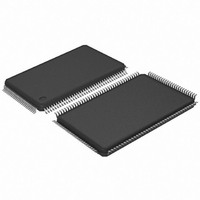
AT91SAM7SE256-AU Atmel, AT91SAM7SE256-AU Datasheet - Page 660

AT91SAM7SE256-AU
Manufacturer Part Number
AT91SAM7SE256-AU
Description
IC ARM7 MCU FLASH 256K 128-LQFP
Manufacturer
Atmel
Series
AT91SAMr
Datasheets
1.AT88SC-SDK1.pdf
(90 pages)
2.AT91SAM7SE256-AU.pdf
(673 pages)
3.AT91SAM7SE32-AU.pdf
(655 pages)
Specifications of AT91SAM7SE256-AU
Core Processor
ARM7
Core Size
16/32-Bit
Speed
55MHz
Connectivity
EBI/EMI, I²C, SPI, SSC, UART/USART, USB
Peripherals
Brown-out Detect/Reset, POR, PWM, WDT
Number Of I /o
88
Program Memory Size
256KB (256K x 8)
Program Memory Type
FLASH
Ram Size
32K x 8
Voltage - Supply (vcc/vdd)
1.65 V ~ 1.95 V
Data Converters
A/D 8x10b
Oscillator Type
Internal
Operating Temperature
-40°C ~ 85°C
Package / Case
128-LQFP
Processor Series
AT91SAMx
Core
ARM7TDMI
Data Bus Width
32 bit
Data Ram Size
32 KB
Interface Type
SPI, TWI, USART
Maximum Clock Frequency
55 MHz
Number Of Programmable I/os
88
Number Of Timers
2
Operating Supply Voltage
3 V to 3.6 V
Maximum Operating Temperature
+ 85 C
Mounting Style
SMD/SMT
3rd Party Development Tools
JTRACE-ARM-2M, KSK-AT91SAM7S-PL, MDK-ARM, RL-ARM, ULINK2
Development Tools By Supplier
AT91SAM-ICE, AT91-ISP, AT91SAM7SE-EK
Minimum Operating Temperature
- 40 C
On-chip Adc
10 bit, 8 Channel
Controller Family/series
AT91SAM7xxxxx
No. Of I/o's
88
Ram Memory Size
32KB
Cpu Speed
48MHz
No. Of Timers
3
Rohs Compliant
Yes
For Use With
AT91SAM7SE-EK - EVAL BOARD FOR AT91SAM7SEAT91SAM-ICE - EMULATOR FOR AT91 ARM7/ARM9
Lead Free Status / RoHS Status
Lead free / RoHS Compliant
Eeprom Size
-
Lead Free Status / Rohs Status
Lead free / RoHS Compliant
Available stocks
Company
Part Number
Manufacturer
Quantity
Price
Company:
Part Number:
AT91SAM7SE256-AU
Manufacturer:
ATMEL
Quantity:
165
- Current page: 660 of 673
- Download datasheet (11Mb)
660
Version
6222D
Version
6222C
SAM7SE512/256/32 Preliminary
Figure 8-1 ”SAM7SE Memory
shown with EBI Chip Select 2
Section 8.1.2.1 ”Flash
Section 6. ”I/O Lines
updated.
PMC
Section 29.9.10 ”PMC Master Clock
TWI
Important changes to this datasheet include a clarification of Atmel TWI compatibility with I2C Standard. (See
Section 32.1 ”Overview”
Section 32.7 ”Master
bit field description modification etc.
Figure 32-2 ”Application Block
Figure 32-5 ”Master Mode Typical Application Block
New sections;
“Transmitting Data”. See also:
Section 32.7.6 ”Internal Address”
32.7.6.2 ”10-bit Slave Addressing”
Section 32.9.6 ”Read Write
Fixed typo in ARBLST bit fields;
Interrupt Mask Register”
Inserted EOSACC bit field description in
Comments
Overview:
Comments
“Two Wire Interface (TWI)”
the datasheet:
(32.7.7 “Using The Peripheral DMA Controller (PDC)” removed from
numbering effected.
(32.9.45 “PDC” removed from
Table 32-4, “Register
Section 32.10.6 ”TWI Status
removed.
Section 32.10.7 ”TWI Interrupt Enable
descriptions removed.
Section 32.10.8 ”TWI Interrupt Disable
descriptions removed.
Section 32.10.9 ”TWI Interrupt Mask
descriptions removed.
Section 32.7.4 ”Master Transmitter Mode”
page
Considerations”,
Mode”, rewritten. New Master Read-write flowcharts, new Read-write transfer waveforms,
353,
Overview”, updated AT91SAM7SE32 ...”reads as 8192 32-bit words.”
Mapping”, reserved offset for PDC removed
and
page
Flowcharts”, updated and new flowcharts added.
Table
Erroneous text references to PDC functionality removed from the TWI section of
Register”, TXBUFE, RXBUFF, ENDTX, ENDRX bit fields and descriptions
Mapping”, Compact Flash not shown w/EBI Chip Select 5. Compact Flash is
Figure
Diagram”, updated
page
355.
“TWI Interrupt Enable
added and includes,
See also:
32-1)
Register”, MDIV removed from bit fields 9 and 8.
368), subsequent chapter numbering effected.
32-6,
Register”,TXBUFE, RXBUFF, ENDTX, ENDRX bit fields and
“JTAG Port Pins”,“Test Pin”,“Reset Pin”,“ERASE
Register”, TXBUFE, RXBUFF, ENDTX, ENDRX bit fields and
Register”,TXBUFE, RXBUFF, ENDTX, ENDRX bit fields and
“TWI Interrupt Enable Register”
Figure
Figure
32-7,
32-11,
Diagram”, updated
Section 32.7.6.1 ”7-bit Slave Addressing”
Register”,
Figure
and
Figure 32-12
Section 32.7.5 ”Master Receiver Mode”
32-8,
“TWI Interrupt Disable Register”
Figure 32-9
page
and
357), subsequent chapter
Figure 32-13
and
Figure 32-10
Pin”; descriptions
and
and
Section
replace
“TWI
6222F–ATARM–14-Jan-11
Change
Request
Ref.
5187
Change
Request
Ref.
4804
4512
5062
4766
4373
4584
4586
Related parts for AT91SAM7SE256-AU
Image
Part Number
Description
Manufacturer
Datasheet
Request
R

Part Number:
Description:
EVAL BOARD FOR AT91SAM7SE
Manufacturer:
Atmel
Datasheet:

Part Number:
Description:
KIT EVAL FOR ARM AT91SAM7S
Manufacturer:
Atmel
Datasheet:

Part Number:
Description:
MCU, MPU & DSP Development Tools KICKSTART KIT ATMEL AT91SAM7S
Manufacturer:
IAR Systems

Part Number:
Description:
MCU ARM9 64K SRAM 144-LFBGA
Manufacturer:
Atmel
Datasheet:

Part Number:
Description:
IC ARM7 MCU FLASH 256K 100LQFP
Manufacturer:
Atmel
Datasheet:

Part Number:
Description:
IC ARM9 MPU 217-LFBGA
Manufacturer:
Atmel
Datasheet:

Part Number:
Description:
MCU ARM9 ULTRA LOW PWR 217-LFBGA
Manufacturer:
Atmel
Datasheet:

Part Number:
Description:
MCU ARM9 324-TFBGA
Manufacturer:
Atmel
Datasheet:

Part Number:
Description:
IC MCU ARM9 SAMPLING 217CBGA
Manufacturer:
Atmel
Datasheet:

Part Number:
Description:
IC ARM9 MCU 217-LFBGA
Manufacturer:
Atmel
Datasheet:

Part Number:
Description:
IC ARM9 MCU 208-PQFP
Manufacturer:
Atmel
Datasheet:

Part Number:
Description:
MCU ARM 512K HS FLASH 100-LQFP
Manufacturer:
Atmel
Datasheet:

Part Number:
Description:
MCU ARM 512K HS FLASH 100-TFBGA
Manufacturer:
Atmel
Datasheet:

Part Number:
Description:
IC ARM9 MCU 200 MHZ 324-TFBGA
Manufacturer:
Atmel
Datasheet:

Part Number:
Description:
IC ARM MCU 16BIT 128K 256BGA
Manufacturer:
Atmel
Datasheet:


