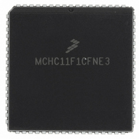
MCHC11F1CFNE3 Freescale Semiconductor, MCHC11F1CFNE3 Datasheet - Page 11

MCHC11F1CFNE3
Manufacturer Part Number
MCHC11F1CFNE3
Description
IC MCU 8BIT 1K RAM 68-PLCC
Manufacturer
Freescale Semiconductor
Series
HC11r
Specifications of MCHC11F1CFNE3
Core Processor
HC11
Core Size
8-Bit
Speed
3MHz
Connectivity
SCI, SPI
Peripherals
POR, WDT
Number Of I /o
30
Program Memory Type
ROMless
Eeprom Size
512 x 8
Ram Size
1K x 8
Voltage - Supply (vcc/vdd)
4.75 V ~ 5.25 V
Data Converters
A/D 8x8b
Oscillator Type
Internal
Operating Temperature
-40°C ~ 85°C
Package / Case
68-PLCC
A/d Inputs
8-Channel, 8-Bit
Eeprom Memory
512 Bytes
Input Output
30
Interface
SCI/SPI
Memory Type
EPROM
Number Of Bits
8
Package Type
68-pin PLCC
Programmable Memory
0 Bytes
Timers
3-16-bit
Voltage, Range
3-5.5 V
Controller Family/series
68HC11
No. Of I/o's
30
Eeprom Memory Size
512Byte
Ram Memory Size
1KB
Cpu Speed
3MHz
No. Of Timers
1
Embedded Interface Type
SCI, SPI
Rohs Compliant
Yes
Processor Series
HC11F
Core
HC11
Data Bus Width
8 bit
Program Memory Size
512 B
Data Ram Size
1 KB
Interface Type
SCI, SPI
Maximum Clock Frequency
3 MHz
Number Of Timers
1
Maximum Operating Temperature
+ 85 C
Mounting Style
SMD/SMT
Minimum Operating Temperature
- 40 C
On-chip Adc
8 bit, 8 Channel
Lead Free Status / RoHS Status
Lead free / RoHS Compliant
Program Memory Size
-
Lead Free Status / Rohs Status
RoHS Compliant part
Available stocks
Company
Part Number
Manufacturer
Quantity
Price
Company:
Part Number:
MCHC11F1CFNE3
Manufacturer:
FREESCALE
Quantity:
5 530
Company:
Part Number:
MCHC11F1CFNE3
Manufacturer:
FREESCALE
Quantity:
5 530
Company:
Part Number:
MCHC11F1CFNE3
Manufacturer:
Freescale Semiconductor
Quantity:
10 000
Company:
Part Number:
MCHC11F1CFNE3R
Manufacturer:
Freescale Semiconductor
Quantity:
10 000
Table
2-1
3-1
3-2
4-1
4-2
4-3
4-4
4-5
4-6
4-7
4-8
4-9
4-10
4-11
4-12
5-1
5-2
5-3
5-4
5-5
6-1
7-1
7-2
8-1
9-1
9-2
9-3
9-4
9-5
9-6
10-1
10-2
A-1
A-2
A-3
A-4
A-5
A-6
A-7
A-8
A-9
TECHNICAL DATA
Port Signal Functions ...................................................................................... 2-7
Reset Vector Comparison ............................................................................... 3-5
Instruction Set ................................................................................................. 3-9
Register and Control Bit Assignments............................................................. 4-5
Write Access Limited Registers....................................................................... 4-7
Hardware Mode Select Summary ................................................................... 4-7
EEPROM Mapping ........................................................................................ 4-10
RAM and Register Mapping .......................................................................... 4-11
EEPROM Block Protection............................................................................ 4-14
EEPROM Erase Mode Control...................................................................... 4-17
Chip Select Clock Stretch Control ................................................................. 4-20
Program Chip Select Size Control................................................................. 4-21
General-Purpose Chip Select Starting Address ............................................ 4-22
General-Purpose Chip Select Size Control ................................................... 4-22
Chip Select Control Parameter Summary ..................................................... 4-23
COP Timer Rate Selection .............................................................................. 5-2
Reset Cause, Operating Mode, and Reset Vector .......................................... 5-4
Highest Priority Interrupt Selection.................................................................. 5-8
Interrupt and Reset Vector Assignments......................................................... 5-9
Stacking Order on Entry to Interrupts............................................................ 5-10
I/O Port Configuration...................................................................................... 6-1
Baud Rate Prescaler Selection ....................................................................... 7-8
Baud Rate Selection........................................................................................ 7-9
SPI Clock Rates .............................................................................................. 8-6
Timer Summary............................................................................................... 9-3
Timer Output Compare Configuration ........................................................... 9-10
Timer Prescaler Selection ............................................................................. 9-12
RTI Rate Selection ........................................................................................ 9-13
Pulse Accumulator Timing............................................................................. 9-16
Pulse Accumulator Edge Detection Control .................................................. 9-17
A/D Converter Channel Assignments............................................................ 10-6
A/D Converter Channel Selection ................................................................. 10-8
Maximum Ratings............................................................................................ A-1
Thermal Characteristics .................................................................................. A-2
DC Electrical Characteristics........................................................................... A-3
Control Timing ................................................................................................. A-5
Peripheral Port Timing................................................................................... A-10
Analog-To-Digital Converter Characteristics ................................................. A-11
Expansion Bus Timing................................................................................... A-12
Serial Peripheral Interface Timing ................................................................. A-14
EEPROM Characteristics .............................................................................. A-17
Freescale Semiconductor, Inc.
For More Information On This Product,
Go to: www.freescale.com
LIST OF TABLES
Title
Page


