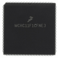
MCHC11F1CFNE3 Freescale Semiconductor, MCHC11F1CFNE3 Datasheet - Page 64

MCHC11F1CFNE3
Manufacturer Part Number
MCHC11F1CFNE3
Description
IC MCU 8BIT 1K RAM 68-PLCC
Manufacturer
Freescale Semiconductor
Series
HC11r
Specifications of MCHC11F1CFNE3
Core Processor
HC11
Core Size
8-Bit
Speed
3MHz
Connectivity
SCI, SPI
Peripherals
POR, WDT
Number Of I /o
30
Program Memory Type
ROMless
Eeprom Size
512 x 8
Ram Size
1K x 8
Voltage - Supply (vcc/vdd)
4.75 V ~ 5.25 V
Data Converters
A/D 8x8b
Oscillator Type
Internal
Operating Temperature
-40°C ~ 85°C
Package / Case
68-PLCC
A/d Inputs
8-Channel, 8-Bit
Eeprom Memory
512 Bytes
Input Output
30
Interface
SCI/SPI
Memory Type
EPROM
Number Of Bits
8
Package Type
68-pin PLCC
Programmable Memory
0 Bytes
Timers
3-16-bit
Voltage, Range
3-5.5 V
Controller Family/series
68HC11
No. Of I/o's
30
Eeprom Memory Size
512Byte
Ram Memory Size
1KB
Cpu Speed
3MHz
No. Of Timers
1
Embedded Interface Type
SCI, SPI
Rohs Compliant
Yes
Processor Series
HC11F
Core
HC11
Data Bus Width
8 bit
Program Memory Size
512 B
Data Ram Size
1 KB
Interface Type
SCI, SPI
Maximum Clock Frequency
3 MHz
Number Of Timers
1
Maximum Operating Temperature
+ 85 C
Mounting Style
SMD/SMT
Minimum Operating Temperature
- 40 C
On-chip Adc
8 bit, 8 Channel
Lead Free Status / RoHS Status
Lead free / RoHS Compliant
Program Memory Size
-
Lead Free Status / Rohs Status
RoHS Compliant part
Available stocks
Company
Part Number
Manufacturer
Quantity
Price
Company:
Part Number:
MCHC11F1CFNE3
Manufacturer:
FREESCALE
Quantity:
5 530
Company:
Part Number:
MCHC11F1CFNE3
Manufacturer:
FREESCALE
Quantity:
5 530
Company:
Part Number:
MCHC11F1CFNE3
Manufacturer:
Freescale Semiconductor
Quantity:
10 000
Company:
Part Number:
MCHC11F1CFNE3R
Manufacturer:
Freescale Semiconductor
Quantity:
10 000
5.1.3 Computer Operating Properly (COP) Reset
COPRST — Arm/Reset COP Timer Circuitry
5.1.4 Clock Monitor Reset
5-2
RESET:
The MCU includes a COP system to help protect against software failures. When the
COP is enabled, the software is responsible for keeping a free-running watchdog timer
from timing out. When the software is no longer being executed in the intended se-
quence, a system reset is initiated.
The state of the NOCOP bit in the CONFIG register determines whether the COP sys-
tem is enabled or disabled. To change the enable status of the COP system, change
the contents of the CONFIG register and then perform a system reset. In the special
test and bootstrap operating modes, the COP system is initially inhibited by the disable
resets (DISR) control bit in the TEST1 register. The DISR bit can subsequently be writ-
ten to zero to enable COP resets.
The COP timer rate control bits CR[1:0] in the OPTION register determine the COP
time-out period. The system E clock is divided by the values shown in Table 5-1. After
reset, these bits are zero, which selects the fastest time-out period. In normal operat-
ing modes, these bits can only be written once within 64 bus cycles after reset.
Complete the following reset sequence to service the COP timer. Write $55 to CO-
PRST to arm the COP timer clearing mechanism. Then write $AA to COPRST to clear
the COP timer. Performing instructions between these two steps is possible as long
as both steps are completed in the correct sequence before the timer times out.
The clock monitor circuit is based on an internal RC time delay. If no MCU clock edges
are detected within this RC time delay, the clock monitor can optionally generate a sys-
tem reset. The clock monitor function is enabled or disabled by the CME and FCME
control bits in the OPTION register. The presence of a time-out is determined by the
RC delay, which allows the clock monitor to operate without any MCU clocks.
Clock monitor is used as a backup for the COP system. Because the COP needs a
clock to function, it is disabled when the clocks stop. Therefore, the clock monitor sys-
tem can detect clock failures not detected by the COP system.
CR[1:0]
0 0
0 1
1 0
1 1
Bit 7
7
0
Divide
E By
2
2
2
2
E =
6
6
0
15
17
19
21
Freescale Semiconductor, Inc.
Table 5-1 COP Timer Rate Selection
For More Information On This Product,
XTAL = 8.0 MHz Time-
5
5
0
–0 ms, +16.4 ms
RESETS AND INTERRUPTS
Go to: www.freescale.com
16.384 ms
65.536 ms
262.14 ms
2.0 MHz
1.049 s
out
4
4
0
3
0
3
XTAL = 12.0 MHz
–0 ms, +10.9 ms
10.923 ms
43.691 ms
174.76 ms
699.05 ms
Time-out
3.0 MHz
2
2
0
1
1
0
XTAL = 16.0 MHz
TECHNICAL DATA
–0 ms, +8.2 ms
Bit 0
32.768 ms
131.07 ms
524.29 ms
0
0
Time-out
8.192 ms
4.0 MHz
MC68HC11F1
$103A


