TV04A640JB-G Comchip Technology, TV04A640JB-G Datasheet - Page 11
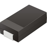
TV04A640JB-G
Manufacturer Part Number
TV04A640JB-G
Description
TVS 400W 64V BIDIRECT SMA
Manufacturer
Comchip Technology
Specifications of TV04A640JB-G
Voltage - Reverse Standoff (typ)
64V
Voltage - Breakdown
71.1V
Power (watts)
400W
Polarization
Bidirectional
Mounting Type
Surface Mount
Package / Case
DO-214AC, SMA
Channels
1 Channel
Clamping Voltage
103 V
Operating Voltage
3.5 V
Breakdown Voltage
71.1 V
Peak Surge Current
40 A
Peak Pulse Power Dissipation
400 W
Lead Free Status / RoHS Status
Lead free / RoHS Compliant


6. Spansion SPI Modes
September 8, 2009 S25FL128P_00_08
A microcontroller can use either of its two SPI modes to control Spansion SPI Flash memory devices:
Input data is latched in on the rising edge of SCK, and output data is available from the falling edge of SCK for
both modes.
When the bus master is in standby mode, SCK is as shown in
Note
The Write Protect/Accelerated Programming (WP#/ACC) and Hold (HOLD#) signals should be driven high (logic level 1) or low (logic level 0)
as appropriate.
Mode 0
Mode 3
CPOL = 0, CPHA = 0 (Mode 0)
CPOL = 1, CPHA = 1 (Mode 3)
SCK remains at 0 for (CPOL = 0, CPHA = 0 Mode 0)
SCK remains at 1 for (CPOL = 1, CPHA = 1 Mode 3)
CS3
SPI Interface with
(CPOL, CPHA) =
Bus Master
(0, 0) or (1, 1)
CPOL
CS2
0
1
CS1
CPHA
0
1
Figure 6.1 Bus Master and Memory Devices on the SPI Bus
SCK
SCK
CS#
D a t a
SO
SO
SI
SCK
SI
S h e e t
Figure 6.2 SPI Modes Supported
MSB
CS#
SCK SO SI
S25FL128P
SPI Memory
WP#/ACC
Device
HOLD#
CS#
SCK SO SI
Figure 6.2
SPI Memory
WP#/ACC
Device
for each of the two modes:
HOLD#
MSB
CS#
SCK SO SI
SPI Memory
WP#/ACC
Device
HOLD#
11
Related parts for TV04A640JB-G
Image
Part Number
Description
Manufacturer
Datasheet
Request
R

Part Number:
Description:
Manufacturer:
Comchip Technology Corporation
Datasheet:
Part Number:
Description:
Manufacturer:
Comchip Technology Corporation
Datasheet:
Part Number:
Description:
Manufacturer:
Comchip Technology Corporation
Datasheet:
Part Number:
Description:
Manufacturer:
Comchip Technology Corporation
Datasheet:
Part Number:
Description:
Manufacturer:
Comchip Technology Corporation
Datasheet:
Part Number:
Description:
Manufacturer:
Comchip Technology Corporation
Datasheet:
Part Number:
Description:
Manufacturer:
Comchip Technology Corporation
Datasheet:
Part Number:
Description:
Manufacturer:
Comchip Technology Corporation
Datasheet:
Part Number:
Description:
Manufacturer:
Comchip Technology Corporation
Datasheet:
Part Number:
Description:
Manufacturer:
Comchip Technology Corporation
Datasheet:
Part Number:
Description:
Manufacturer:
Comchip Technology Corporation
Datasheet:
Part Number:
Description:
Manufacturer:
Comchip Technology Corporation
Datasheet:
Part Number:
Description:
Manufacturer:
Comchip Technology Corporation
Datasheet:
Part Number:
Description:
Manufacturer:
Comchip Technology Corporation
Datasheet:
Part Number:
Description:
Manufacturer:
Comchip Technology Corporation
Datasheet: