TV04A640JB-G Comchip Technology, TV04A640JB-G Datasheet - Page 20
TV04A640JB-G
Manufacturer Part Number
TV04A640JB-G
Description
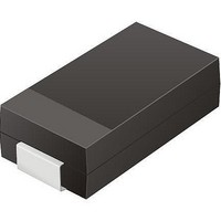
TVS 400W 64V BIDIRECT SMA
Manufacturer
Comchip Technology
Specifications of TV04A640JB-G
Voltage - Reverse Standoff (typ)
64V
Voltage - Breakdown
71.1V
Power (watts)
400W
Polarization
Bidirectional
Mounting Type
Surface Mount
Package / Case
DO-214AC, SMA
Channels
1 Channel
Clamping Voltage
103 V
Operating Voltage
3.5 V
Breakdown Voltage
71.1 V
Peak Surge Current
40 A
Peak Pulse Power Dissipation
400 W
Lead Free Status / RoHS Status
Lead free / RoHS Compliant


20
11.1.2
Parallel Mode
In parallel mode, the maximum SCK clock frequency is 6 MHz. The device requires a single clock cycle
instead of eight clock cycles to access the next data byte. The memory array output will be the same as in the
serial mode. The only difference is that a byte of data is output per clock cycle instead of a single bit. This
means that 256 bytes of data can be copied into the 256 byte wide page write buffer in 256 clock cycles
instead of in 2,048 clock cycles.
Notes
1. 1st Byte = “03h”.
2. 2nd Byte = Address 1, MSB first (bits 23 through 16).
3. 3rd Byte = Address 2, MSB first (bits 15 through 8).
4. 4th Byte = Address 3, MSB first (bits 7 through 0).
5. From the 5th Byte, SO will output the array data.
6. In parallel mode, the maximum clock frequency (Fsck) is 6 MHz.
7. For parallel mode operation, the device requires an Enter Parallel Mode command (55h) before the READ command. An Exit Parallel
Mode (45h) command or a power-down / power-up sequence is required to exit the parallel mode.
PO[7-0]
SCK
CS#
SI
Figure 11.2 Parallel Read Instruction Sequence
Instruction
High Impedance
S25FL128P
D a t a
S h e e t
24-Bit
Address
S25FL128P_00_08 September 8, 2009
Data Out
Related parts for TV04A640JB-G
Image
Part Number
Description
Manufacturer
Datasheet
Request
R

Part Number:
Description:
Manufacturer:
Comchip Technology Corporation
Datasheet:
Part Number:
Description:
Manufacturer:
Comchip Technology Corporation
Datasheet:
Part Number:
Description:
Manufacturer:
Comchip Technology Corporation
Datasheet:
Part Number:
Description:
Manufacturer:
Comchip Technology Corporation
Datasheet:
Part Number:
Description:
Manufacturer:
Comchip Technology Corporation
Datasheet:
Part Number:
Description:
Manufacturer:
Comchip Technology Corporation
Datasheet:
Part Number:
Description:
Manufacturer:
Comchip Technology Corporation
Datasheet:
Part Number:
Description:
Manufacturer:
Comchip Technology Corporation
Datasheet:
Part Number:
Description:
Manufacturer:
Comchip Technology Corporation
Datasheet:
Part Number:
Description:
Manufacturer:
Comchip Technology Corporation
Datasheet:
Part Number:
Description:
Manufacturer:
Comchip Technology Corporation
Datasheet:
Part Number:
Description:
Manufacturer:
Comchip Technology Corporation
Datasheet:
Part Number:
Description:
Manufacturer:
Comchip Technology Corporation
Datasheet:
Part Number:
Description:
Manufacturer:
Comchip Technology Corporation
Datasheet:
Part Number:
Description:
Manufacturer:
Comchip Technology Corporation
Datasheet: