TV04A640JB-G Comchip Technology, TV04A640JB-G Datasheet - Page 40
TV04A640JB-G
Manufacturer Part Number
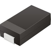
TV04A640JB-G
Description
TVS 400W 64V BIDIRECT SMA
Manufacturer
Comchip Technology
Specifications of TV04A640JB-G
Voltage - Reverse Standoff (typ)
64V
Voltage - Breakdown
71.1V
Power (watts)
400W
Polarization
Bidirectional
Mounting Type
Surface Mount
Package / Case
DO-214AC, SMA
Channels
1 Channel
Clamping Voltage
103 V
Operating Voltage
3.5 V
Breakdown Voltage
71.1 V
Peak Surge Current
40 A
Peak Pulse Power Dissipation
400 W
Lead Free Status / RoHS Status
Lead free / RoHS Compliant


14. Initial Delivery State
15. Absolute Maximum Ratings
40
The device is delivered with all bits set to 1 (each byte contains FFh) upon initial factory shipment. The Status
Register contains 00h (all Status Register bits are 0).
Do not stress the device beyond the ratings listed in this section, or serious, permanent damage to the device
may result. These are stress ratings only and device operation at these or any other conditions beyond those
indicated in this section and in the
operation for extended periods at the limits listed in this section may affect device reliability.
Notes
1. Minimum DC voltage on input or I/O pins is –0.5 V. During voltage transitions, input at I/O pins may overshoot V
2. No more than one output may be shorted to ground at a time. Duration of the short circuit should not be greater than one second.
3. Stresses above those listed under
Ambient Storage Temperature
Voltage with Respect to Ground: All Inputs and I/Os
up to 20 ns. See
to V
functional operation of the device at these or any other conditions above those indicated in the operational sections of this data sheet is not
implied. Exposure of the device to absolute maximum rating conditions for extended periods may affect device reliability.
V
CC
V
Symbol
V
CC
CC
CC(min)
(cut-off)
t
t
PU
PD
+ 2.0V for periods up to 20 ns. See
(low)
Figure
V
V
V
V
V
V
CC
CC
CC
CC
CC
CC
15.2. Maximum DC voltage on output and I/O pins is 3.6 V. During voltage transitions output pins may overshoot
(minimum operation voltage)
(Cut off where re-initialization is needed)
(Low voltage for initialization to occur at read/standby)
(Low voltage for initialization to occur at embedded)
(min) to device operation
(low duration time)
Description
Table 13.1 Power-Up / Power-Down Voltage and Timing
Figure 15.1 Maximum Negative Overshoot Waveform
+0.8 V
–0.5 V
–2 V
Absolute Maximum Ratings
Operating Ranges
Table 15.1 Absolute Maximum Ratings
Figure
S25FL128P
15.2.
Parameter
D a t a
20 ns
may cause permanent damage to the device. This is a stress rating only;
section of this document is not implied. Device
S h e e t
20 ns
20 ns
S25FL128P_00_08 September 8, 2009
–0.5V to V
–65°C to +150°C
Rating
Min
300
2.7
2.4
0.2
2.3
1.0
CC
+0.5V
SS
Max
to –2.0V for periods of
Unit
µs
µs
V
V
V
Related parts for TV04A640JB-G
Image
Part Number
Description
Manufacturer
Datasheet
Request
R

Part Number:
Description:
Manufacturer:
Comchip Technology Corporation
Datasheet:
Part Number:
Description:
Manufacturer:
Comchip Technology Corporation
Datasheet:
Part Number:
Description:
Manufacturer:
Comchip Technology Corporation
Datasheet:
Part Number:
Description:
Manufacturer:
Comchip Technology Corporation
Datasheet:
Part Number:
Description:
Manufacturer:
Comchip Technology Corporation
Datasheet:
Part Number:
Description:
Manufacturer:
Comchip Technology Corporation
Datasheet:
Part Number:
Description:
Manufacturer:
Comchip Technology Corporation
Datasheet:
Part Number:
Description:
Manufacturer:
Comchip Technology Corporation
Datasheet:
Part Number:
Description:
Manufacturer:
Comchip Technology Corporation
Datasheet:
Part Number:
Description:
Manufacturer:
Comchip Technology Corporation
Datasheet:
Part Number:
Description:
Manufacturer:
Comchip Technology Corporation
Datasheet:
Part Number:
Description:
Manufacturer:
Comchip Technology Corporation
Datasheet:
Part Number:
Description:
Manufacturer:
Comchip Technology Corporation
Datasheet:
Part Number:
Description:
Manufacturer:
Comchip Technology Corporation
Datasheet:
Part Number:
Description:
Manufacturer:
Comchip Technology Corporation
Datasheet: