TV04A640JB-G Comchip Technology, TV04A640JB-G Datasheet - Page 29
TV04A640JB-G
Manufacturer Part Number
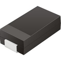
TV04A640JB-G
Description
TVS 400W 64V BIDIRECT SMA
Manufacturer
Comchip Technology
Specifications of TV04A640JB-G
Voltage - Reverse Standoff (typ)
64V
Voltage - Breakdown
71.1V
Power (watts)
400W
Polarization
Bidirectional
Mounting Type
Surface Mount
Package / Case
DO-214AC, SMA
Channels
1 Channel
Clamping Voltage
103 V
Operating Voltage
3.5 V
Breakdown Voltage
71.1 V
Peak Surge Current
40 A
Peak Pulse Power Dissipation
400 W
Lead Free Status / RoHS Status
Lead free / RoHS Compliant


11.8
September 8, 2009 S25FL128P_00_08
Write Status Register (WRSR: 01h)
The Write Status Register (WRSR) command changes the bits in the Status Register. A Write Enable
(WREN) command, which itself sets the Write Enable Latch (WEL) in the Status Register, is required prior to
writing the WRSR command.
shows the status register bits and their functions.
The host system must drive CS# low, write the WRSR command, and the appropriate data byte on SI
(Figure
The WRSR command cannot change the state of the Write Enable Latch (bit 1). The WREN command must
be used for that purpose. Bit 0 is a status bit controlled internally by the Flash device. Bits 6 and 5 are always
read as 0 and have no user significance.
The WRSR command also controls the value of the Status Register Write Disable (SRWD) bit. The SRWD bit
and WP#/ACC together place the device in the Hardware Protected Mode (HPM). The device ignores all
WRSR commands once it enters the Hardware Protected Mode (HPM).
must be driven low and the SRWD bit must be 1 for this to occur.
Notes
1. Instruction byte = 01h
2. In parallel mode, the maximum access clock frequency (Fsck) is 10 MHz (SCK pin clock frequency).
3. Writing to the Status Register in parallel mode requires a Parallel Mode Entry command (55h) to be issued before the WRSR command.
Once in the parallel mode, the flash memory will not exit the parallel mode until a Parallel Mode Exit (45h) command is given to the flash
device, or upon power-down or power-up sequence.
11.12).
Figure 11.13 Parallel Write Status Register (WRSR) Command Sequence
Figure 11.12 Write Status Register (WRSR) Command Sequence
PO[7-0]
D a t a
SCK
CS#
CS#
SCK
SI
SO
SI
Table 11.3, S25FL128P Status Register (Uniform 256 KB sector) on page 26
Mode 3
Mode 0
Hi-Z
Mode 3
Mode 0
Hi-Z
S h e e t
0
S25FL128P
0
1
1
2
Command
2
Command
3
3
4
4
5
5
6
6
7
MSB
7
Byte 1
7
8 9 10 11 12 13 14 15
8 9 10 11 12 13 14 15
6
Status Register In
5
Status Register In
4
3
2
Table 11.5
1
0
shows that WP#/ACC
29
Related parts for TV04A640JB-G
Image
Part Number
Description
Manufacturer
Datasheet
Request
R

Part Number:
Description:
Manufacturer:
Comchip Technology Corporation
Datasheet:
Part Number:
Description:
Manufacturer:
Comchip Technology Corporation
Datasheet:
Part Number:
Description:
Manufacturer:
Comchip Technology Corporation
Datasheet:
Part Number:
Description:
Manufacturer:
Comchip Technology Corporation
Datasheet:
Part Number:
Description:
Manufacturer:
Comchip Technology Corporation
Datasheet:
Part Number:
Description:
Manufacturer:
Comchip Technology Corporation
Datasheet:
Part Number:
Description:
Manufacturer:
Comchip Technology Corporation
Datasheet:
Part Number:
Description:
Manufacturer:
Comchip Technology Corporation
Datasheet:
Part Number:
Description:
Manufacturer:
Comchip Technology Corporation
Datasheet:
Part Number:
Description:
Manufacturer:
Comchip Technology Corporation
Datasheet:
Part Number:
Description:
Manufacturer:
Comchip Technology Corporation
Datasheet:
Part Number:
Description:
Manufacturer:
Comchip Technology Corporation
Datasheet:
Part Number:
Description:
Manufacturer:
Comchip Technology Corporation
Datasheet:
Part Number:
Description:
Manufacturer:
Comchip Technology Corporation
Datasheet:
Part Number:
Description:
Manufacturer:
Comchip Technology Corporation
Datasheet: