TV04A640JB-G Comchip Technology, TV04A640JB-G Datasheet - Page 36
TV04A640JB-G
Manufacturer Part Number
TV04A640JB-G
Description
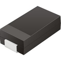
TVS 400W 64V BIDIRECT SMA
Manufacturer
Comchip Technology
Specifications of TV04A640JB-G
Voltage - Reverse Standoff (typ)
64V
Voltage - Breakdown
71.1V
Power (watts)
400W
Polarization
Bidirectional
Mounting Type
Surface Mount
Package / Case
DO-214AC, SMA
Channels
1 Channel
Clamping Voltage
103 V
Operating Voltage
3.5 V
Breakdown Voltage
71.1 V
Peak Surge Current
40 A
Peak Pulse Power Dissipation
400 W
Lead Free Status / RoHS Status
Lead free / RoHS Compliant


11.13 Release from Deep Power Down (RES: ABh)
11.14 Release from Deep Power Down and Read Electronic Signature (RES: ABh)
36
11.14.1
Serial Mode
The device requires the Release from Deep Power Down (RES) command to exit the Deep Power Down
mode. When the device is in the Deep Power Down mode, all commands except RES are ignored.
The host system must drive CS# low and write the RES command to SI. CS# must be driven low for the entire
duration of the sequence. The command sequence is shown in
The host system must drive CS# high t
from DP mode to the standby mode after a delay of t
the device can execute any read or write command.
This command reads the old-style Electronic Signature from the SO serial output pin. See
Table 11.6
consists of the Device ID portion of the 16-bit JEDEC ID that is read by the Read Identifier (RDID) instruction.
The old style Electronic Signature is supported for backward compatibility, and should not be used for new
software designs, which should instead use the JEDEC 16-bit Electronic Signature by issuing the Read
Identifier (RDID) command.
The device is first selected by driving the CS# chip select input pin to the logic low state. The RES command
is shifted in followed by three dummy bytes onto the SI serial input pin. After the last bit of the three dummy
bytes is shifted into the device, a byte of Electronic Signature will be shifted out of the SO serial output pin.
Each bit is shifted out during the falling edge of the SCK serial clock signal. The maximum clock frequency for
the RES (ABh) command is at 104 MHz.
The Electronic Signature can be read repeatedly by applying multiples of eight clock cycles.
The RES instruction sequence is terminated by driving the CS# chip select input pin to the logic high state
anytime during data output. After issuing any Read ID commands (90h, 9Fh, ABh), driving the CS# chip
select input pin to the logic high state will automatically send the device into the standby mode. Driving the
CS# chip select input pin to the logic low state again will automatically send the device out of the standby
mode and into the active mode.
for the command sequence and signature value. Please note that the Electronic Signature only
SO/PO[7-0]
Figure 11.19 Release from Deep Power Down (RES) Command Sequence
SCK
CS#
SI
Mode 3
Mode 0
Hi-Z
RES(max)
S25FL128P
0
D a t a
after the 8-bit RES command byte. The device transitions
1
Deep Power-down Mode
2
RES
S h e e t
Command
3
(see
4
Table 19.1 on page
Figure 11.19
5
6
S25FL128P_00_08 September 8, 2009
7
and
Table
43). In the standby mode,
t
RES
11.6.
Standby Mode
Figure 11.20
and
Related parts for TV04A640JB-G
Image
Part Number
Description
Manufacturer
Datasheet
Request
R

Part Number:
Description:
Manufacturer:
Comchip Technology Corporation
Datasheet:
Part Number:
Description:
Manufacturer:
Comchip Technology Corporation
Datasheet:
Part Number:
Description:
Manufacturer:
Comchip Technology Corporation
Datasheet:
Part Number:
Description:
Manufacturer:
Comchip Technology Corporation
Datasheet:
Part Number:
Description:
Manufacturer:
Comchip Technology Corporation
Datasheet:
Part Number:
Description:
Manufacturer:
Comchip Technology Corporation
Datasheet:
Part Number:
Description:
Manufacturer:
Comchip Technology Corporation
Datasheet:
Part Number:
Description:
Manufacturer:
Comchip Technology Corporation
Datasheet:
Part Number:
Description:
Manufacturer:
Comchip Technology Corporation
Datasheet:
Part Number:
Description:
Manufacturer:
Comchip Technology Corporation
Datasheet:
Part Number:
Description:
Manufacturer:
Comchip Technology Corporation
Datasheet:
Part Number:
Description:
Manufacturer:
Comchip Technology Corporation
Datasheet:
Part Number:
Description:
Manufacturer:
Comchip Technology Corporation
Datasheet:
Part Number:
Description:
Manufacturer:
Comchip Technology Corporation
Datasheet:
Part Number:
Description:
Manufacturer:
Comchip Technology Corporation
Datasheet: