TV04A640JB-G Comchip Technology, TV04A640JB-G Datasheet - Page 3
TV04A640JB-G
Manufacturer Part Number
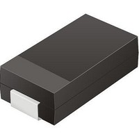
TV04A640JB-G
Description
TVS 400W 64V BIDIRECT SMA
Manufacturer
Comchip Technology
Specifications of TV04A640JB-G
Voltage - Reverse Standoff (typ)
64V
Voltage - Breakdown
71.1V
Power (watts)
400W
Polarization
Bidirectional
Mounting Type
Surface Mount
Package / Case
DO-214AC, SMA
Channels
1 Channel
Clamping Voltage
103 V
Operating Voltage
3.5 V
Breakdown Voltage
71.1 V
Peak Surge Current
40 A
Peak Pulse Power Dissipation
400 W
Lead Free Status / RoHS Status
Lead free / RoHS Compliant


Distinctive Characteristics
General Description
This document states the current technical specifications regarding the Spansion product(s) described herein. Spansion Inc. deems the products to have been in sufficient pro-
duction volume such that subsequent versions of this document are not expected to change. However, typographical or specification corrections, or modifications to the valid com-
binations offered may occur.
Architectural Advantages
S25FL128P
128 Megabit CMOS 3.0 Volt Flash Memory
with 104-MHz SPI (Serial Peripheral Interface) Bus
Data Sheet
Single power supply operation
– Full voltage range: 2.7V to 3.6V read and program operations
Memory Architecture
– 128Mb uniform 256 KB sector product
– 128Mb uniform 64 KB sector product
Program
– Page Program (up to 256 bytes) in 1.5 ms (typical)
– Faster program time in Accelerated Programming mode
Erase
– 2 s typical 256 KB sector erase time
– 0.5 s typical 64 KB sector erase time
– 128 s typical bulk erase time
– Sector erase (SE) command (D8h) for 256 KB sectors; (20h or D8h)
– Bulk erase command (C7h) for 256 KB sectors; (60h or C7h) for
Cycling Endurance
– 100,000 cycles per sector typical
Data Retention
– 20 years typical
Device ID
– RDID (9Fh), READ_ID (90h) and RES (ABh) commands to read
– RES command one-byte electronic signature for backward
(8.5 V–9.5 V on #WP/ACC) in 1.2 ms (typical)
for 64KB sectors
64KB sectors
manufacturer and device ID information
compatibility
The S25FL128P is a 3.0 Volt (2.7V to 3.6V), single-power-supply Flash memory device. The device consists
of 64 sectors of 256 KB memory, or 256 sectors of 64 KB memory.
The device accepts data written to SI (Serial Input) and outputs data on SO (Serial Output). The devices are
designed to be programmed in-system with the standard system 3.0 volt V
The memory can be programmed 1 to 256 bytes at a time, using the Page Program command. The device
supports Sector Erase and Bulk Erase commands.
Each device requires only a 3.0 volt power supply (2.7V to 3.6V) for both read and write functions. Internally
generated and regulated voltages are provided for the program operations. This device requires a high
voltage supply to WP#/ACC pin for the Accelerated Programming mode.
Publication Number S25FL128P_00
Revision 08
Performance Characteristics
Memory Protection Features
Software Features
Hardware Features
Process Technology
– Manufactured on 0.09 µm MirrorBit
Package Option
– Industry Standard Pinouts
– 16-pin SO package (300 mils)
– 8-Contact WSON Package (6 x 8 mm)
Speed
– 104 MHz clock rate (maximum)
Power Saving Standby Mode
– Standby Mode 200 µA (max)
– Deep Power Down Mode 3 µA (typical)
Memory Protection
– WP#/ACC pin works in conjunction with Status Register Bits to
– 256 KB uniform sector product:
– 64KB uniform sector product:
– SPI Bus Compatible Serial Interface
x8 Parallel Programming Mode (for 16-pin SO package only)
protect specified memory areas
Status Register Block Protection bits (BP2, BP1, BP0) in status
register configure parts of memory as read-only.
Status Register Block Protection bits (BP3, BP2, BP1, BP0) in
status register configure parts of memory as read-only
Issue Date September 8, 2009
CC
supply.
®
process technology
Related parts for TV04A640JB-G
Image
Part Number
Description
Manufacturer
Datasheet
Request
R

Part Number:
Description:
Manufacturer:
Comchip Technology Corporation
Datasheet:
Part Number:
Description:
Manufacturer:
Comchip Technology Corporation
Datasheet:
Part Number:
Description:
Manufacturer:
Comchip Technology Corporation
Datasheet:
Part Number:
Description:
Manufacturer:
Comchip Technology Corporation
Datasheet:
Part Number:
Description:
Manufacturer:
Comchip Technology Corporation
Datasheet:
Part Number:
Description:
Manufacturer:
Comchip Technology Corporation
Datasheet:
Part Number:
Description:
Manufacturer:
Comchip Technology Corporation
Datasheet:
Part Number:
Description:
Manufacturer:
Comchip Technology Corporation
Datasheet:
Part Number:
Description:
Manufacturer:
Comchip Technology Corporation
Datasheet:
Part Number:
Description:
Manufacturer:
Comchip Technology Corporation
Datasheet:
Part Number:
Description:
Manufacturer:
Comchip Technology Corporation
Datasheet:
Part Number:
Description:
Manufacturer:
Comchip Technology Corporation
Datasheet:
Part Number:
Description:
Manufacturer:
Comchip Technology Corporation
Datasheet:
Part Number:
Description:
Manufacturer:
Comchip Technology Corporation
Datasheet:
Part Number:
Description:
Manufacturer:
Comchip Technology Corporation
Datasheet: